Software Overview
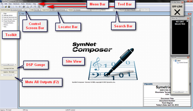
The first screen you see after opening Composer is the Site View screen. Site Files are designed by dragging and dropping objects from the left hand "Toolkit" onto the screen. The Site View screen is just for reference purposes. The only necessary objects are the DSP hardware units. All external hardware icons, pictures, text and wire connections are for documentation purposes only.
Site View
Across the top of the Site View window are the Menu Bar, Tool Bar, Locator Bar, Control Screen Bar and Search Bar. The DSP Gauge shows approximate DSP usage. When online, pressing F2 on the keyboard or clicking on the "Mute All Outputs" button located just below the Toolkit will execute a full system mute.
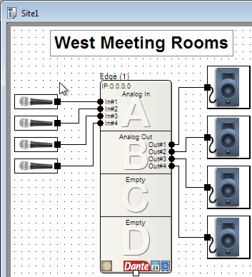
To create a site, first add a DSP unit. Second, add any external hardware icons such as microphones and speakers to help document your system. Finally, add text labels. A simple site is shown below:
Design View
Double clicking on a DSP unit in the Site View will open the Design View for that unit. The Design View is where the DSP programming takes place. Various parts of the Design View are labeled here:
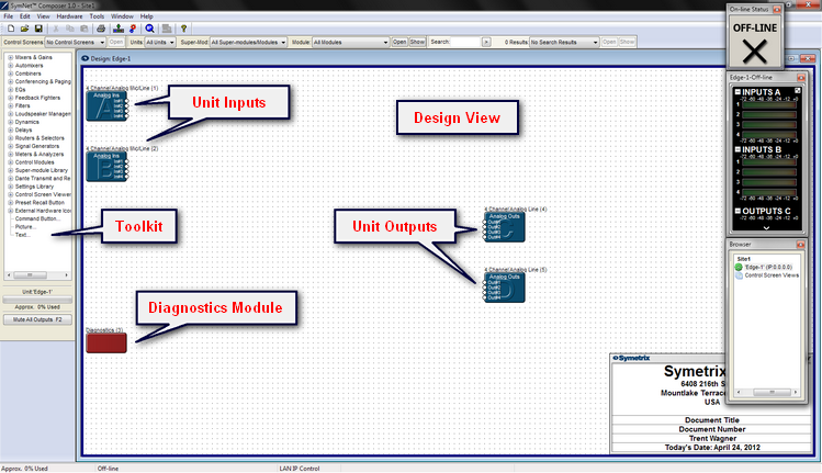
The DSP unit shown is an Edge configured for 8 analog mic/line inputs and 8 analog line outputs. There are two 4-channel Unit Input and two 4-channel Unit Output modules pre-placed on the left and right side of the sheet, respectively. These represent the physical audio I/O and house the controls for configuring the I/O.
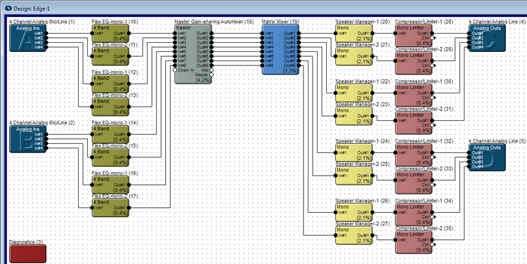
Once again the Toolkit is on the left side, but notice that it has now changed to display primarily DSP and Logic Modules instead of Units. You drag and drop these DSP and Logic Modules into the Design View then wire them up to create your signal flow. A simple design is shown below: