2 Line VoIP Interface Card
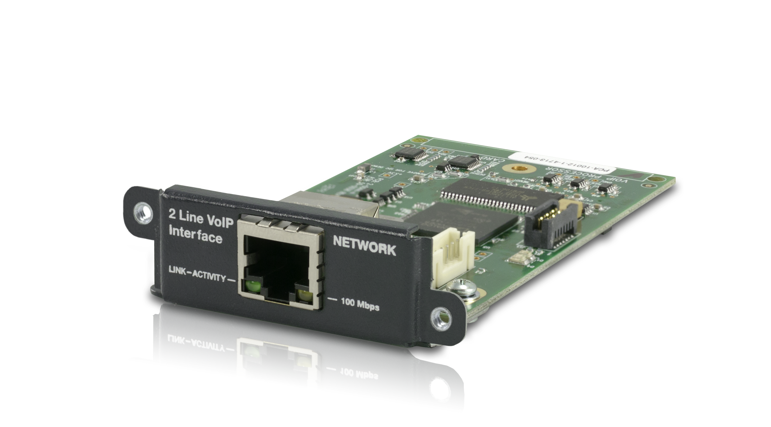
Hardware:
Software:
Installing/Running Composer and Upgrading Firmware
Setting up the VoIP card for use with the Cisco Unified Communications Manager
Setting up the VoIP card for Direct IP Dialing (No PBX)
The 2 Line VoIP Interface Card is a SIP-based plug-in card for the Symetrix Edge, Radius AEC, and Radius 12x8 EX systems that natively integrates with SIP-based call platforms and unified communications environments. The 2 Line VoIP Interface Card supports both narrow-band and wide-band audio, and is capable of a broad range of telephony features including: caller ID, call waiting, call reject, call hold, call transfer, redial, do not disturb, and conferencing. Two independent SIP registrations are provided for two simultaneous independent calls per card.
The 2 Line VoIP Interface Card is designed for conferencing, paging, remote monitoring, and broadcast applications.
Best-In-Class Deployment and Administration
The 2 Line VoIP Interface Card is easy to deploy and manage in a VoIP environment. The intuitive, Web-based configuration software is accessible from both the AV LAN or the VoIP LAN giving IT administrators and integrators easy access to configure and maintain the device.
Market-Leading, Open Standards Interoperability.
Designed for enhanced interoperability, and leveraging and complementing existing IT investments of any enterprise, the 2 Line VoIP Interface delivers high-definition voice quality and a superior Unified Communications experience. The 2 Line VoIP Interface is designed on open SIP standards and has been validated with Cisco and Asterisk SIP-compatible call management platforms.
Multiple Control Options
Symetrix’s SymVue application builder, and extensive third-party control support allows intuitive end-user operation and reduces the amount of time to develop user interfaces.
Upgrade to VoIP
The 2 Line VoIP Interface Card is integrated into the call platform environment with an easy-to-navigate Web interface and is a simple upgrade from existing PSTN solutions. With a common applications programming interface, existing PSTN solutions can be upgraded to VoIP without reprogramming existing third-party control systems.
Benefits of the 2 Line VoIP Interface Card
• Natural-sounding wide-band audio for all applications improves communication and collaboration.
• Leverages existing IT infrastructure investments to reduce telecommunications costs.
• Web-based management access from both the VoIP LAN and AV LAN enables partners to integrate more easily into SIP call management
platforms.
• Backwards-compatible API saves time when integrating with existing control systems.
• Each 2 Line VoIP Interface Card can support two independent rooms, efficient for reconfigurable rooms or for cost effectively supporting
multiple rooms per Symetrix Symetrix device.
• Each line supports two callers for conferencing without an external conferencing service.
2 Line VoIP Interface Card Features and Specification
Audio Features:
• Codecs: G.722, G.711 (A-law and μ-Law), G.729 (including Annex B) and G.723.1
• DTMF tone generation (RFC 2833, SIP Info and in-band).
• Low-delay audio packet transmission.
• Adaptive jitter buffers.
• Independent level adjustments for call progress, DTMF and ring tones.
• Country-specific tone compatibility.
Composer Software Features:
• DTMF decoding and call status logic is natively supported.
Call Handling Features:
• 2 lines (registrations) with independent operation.
• 4 call appearances (4 remote calls, 2 per line).
• Call transfer.
• Call hold.
• URI dialing.
• Call reject.
• Call timer.
• Call waiting.
• Local three-way audio conferencing per line.
• Do not disturb function.
• Local configurable digit map / dial plan.
• On-hook, off-hook, speed dialing, redial.
• Conferencing and splitting of call appearances.
• Auto-answer.
• Calling party identification.
Network and Provisioning:
• One 10/100 Mbps LAN interface.
• Password-protected web management access via VoIP LAN or AV LAN on Symetrix Symetrix Edge and Radius AEC systems.
• IETF SIP (RFC 3261 and companion RFCs).
• Conforms to IEEE802.3-2005 (Clause 40) for Physical Media Attachment.
• Conforms to IEEE802.3-2002 (Clause 28) for Link Partner Auto-Negotiation.
• Manual or dynamic host configuration protocol (DHCP) network setup.
• Network Address Translation (NAT) – support for static configuration and “Keep-Alive” SIP signaling.
• VLAN support.
• QoS Support – IEEE 802.1p/Q tagging (VLAN), and DSCP.
• RTCP support.
• Event logging.
• IPv4.
• TCP and UDP.
Specifications
| Item | Value |
|---|---|
| Connector | RJ45. |
| Ethernet Interface | 10/100 Base-T. |
| Ethernet Cable | Standard CAT5, maximum device to device length = 100 meters. |
Mechanical Data
| Items | Specifications | Remarks |
|---|---|---|
| Shipping Weight | 1 lbs. (0.45 kg) | |
| Certifications or Compliance | UL 60065, cUL 60065, IEC 60065, EN 55103-1, EN 55103-2, FCC Part 15, RoHS, WEEE, | |
| What Ships in the Box | Symetrix I/O card, card bracket, 2 black 4-40 Phillips head screws, 3 stainless steel 4-40 Phillips head screws, a quick start guide. | Field swappable by certified technicians. |
Architect and Engineer Specifications: 2 Line VoIP Interface Card
This device shall provide two VoIP telephone lines to an EDGE or RADIUS AEC frame with standard SIP telephony functions. Up to four of these devices may be installed in a single EDGE frame for up to eight channels of local input and up to one of these devices may be installed in a single RADIUS AEC for two channels of local input. Levels, mutes, and call control shall be controllable via software. VoIP network connection shall be accessible via a rear panel RJ45 Ethernet connector with configuration available both via the VoIP LAN interface and the AV LAN interface.
The device shall comply with CE and FCC Part 15 emissions limits and applicable UL/cUL safety standards. The device shall be RoHS and WEEE compliant and carry a three-year manufacturer’s warranty. The mounting plate shall be constructed of cold rolled steel, and mount into a Symetrix RADIUS AEC or EDGE frame I/O card slot. The device shall be a Symetrix Symetrix 2 Line VoIP Interface Card.
External Connections
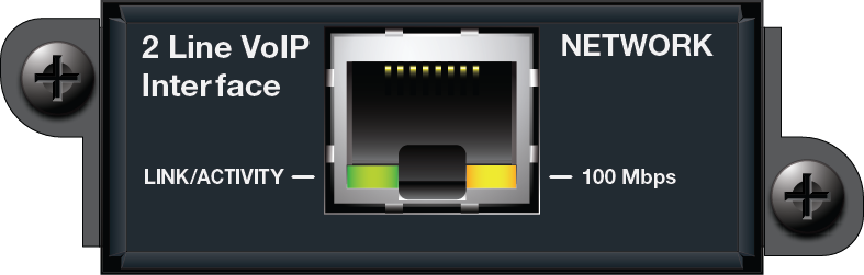
Using a standard CAT5/6 cable terminated with RJ45 connectors, connect one end to the port on the 2 Line VoIP Interface Card and opposite end to the VoIP network. If the VoIP network and AV Network are the same, you can connect one end of the CAT5/6 cable to the port on the 2 Line VoIP Interface Card and the opposite end into the secondary Ethernet port on the Symetrix DSP.
GUI
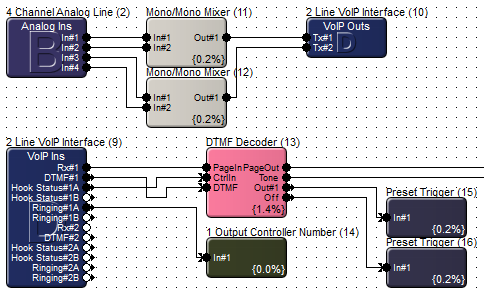
'VoIP Ins' Module
Note: In the above screen shot, "1" and "2" are the Line numbers, and "A" and "B" refer to the first and second call appearances for each line.
Rx - A mix of call progress signals (dial tone, busy tone, ring tone etc.). The call audio received from the far end and user feedback (button presses, etc.).
DTMF – A control signal output for passing DTMF (Dual-Tone Multi-Frequency) tones received from the far end (not dialed locally) to the Symetrix DTMF Decoder Module.
Hook Status - A control signal output indicating whether the line’s call appearance is on-hook (hung up) or off-hook. The signal is High when the line’s call appearance is off-hook.
Ringing - A control signal output indicating whether the line’s call appearance is receiving a call. If the line’s call appearance is ringing this control signal will be High.
Gain Control and Meters
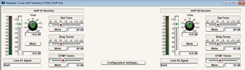
Main Receive Gain Meter and Fader - (The VoIP #1 or VoIP #2 Receive meter and fader). This meter is calibrated in dBFS from -72dB to +0dB. The meter will indicate the level of incoming signal of the input, including Ring, Dial, DTMF tones, and the far end caller. The gain fader and its associated Mute button relate to all incoming signals.
Dial Tone - This gain fader and its associated Mute button relate to the dial tone which is heard when the line is taken off hook. The signal can be adjusted or muted here.
Ring Tones - This gain fader and its associated Mute button relate to the ring tones which will sound when the line is receiving a call. The signal can be adjusted or muted here.
DTMF Tones - This gain fader and its associated Mute button relate to DTMF tones heard in the local room when digits are pressed. The signal can be adjusted or muted here. The DTMF Tone gain fader and mute also affect the user feedback tones when the Delete and Clear buttons are pressed.
Line #1 Signal and Line #2 Signal Labels - User editable field for both of the input channels.
Configuration Settings
The Configuration Settings button is found at the top of the 'VoIP Ins' module GUI. Clicking this button will open a window showing network and registration status information. Settings cannot be changed using this window, however it includes buttons that launch the Web Administration tool.
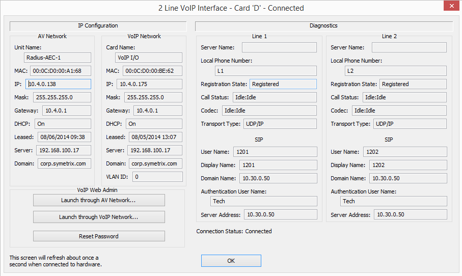
AV Network - Lists the local network settings of the host Edge or Radius AEC device.
VoIP Network - Lists the VoIP card network settings.
The Launch through AV Network… and **Launch through VoIP Network… buttons** launch the VoIP Web Administration tool through the AV and VoIP networks respectively. Having access to the VoIP Web Administration tool from the AV Network simplifies configuring the system. For more information on the Web Admin click here.
The Reset Password button resets the Web Administration password to its default value of “Password”. The user name is always set to “Admin”.
Line 1 and Line 2 - Lists the registration settings for lines 1 and 2.
Note: The Configuration Settings button cannot be exported to SymVue.
Dialer
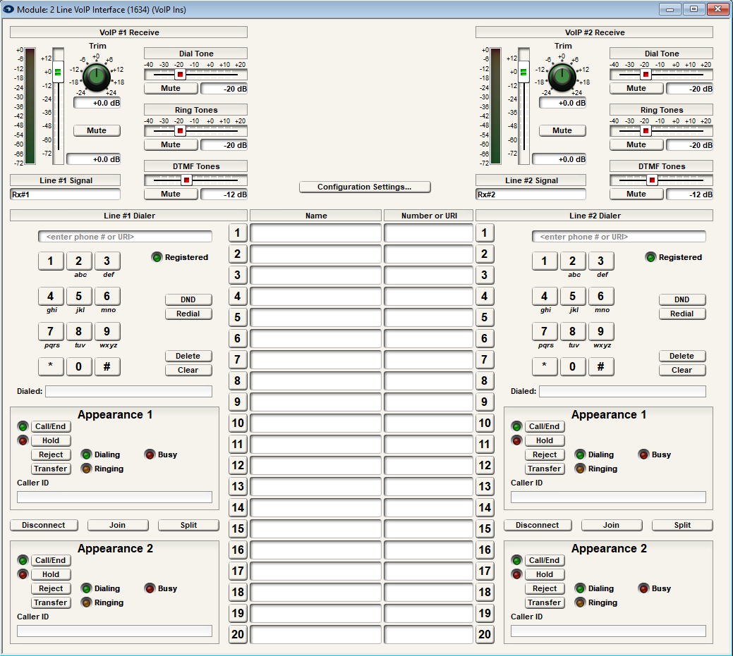
Dialer User Entry Field - (user-editable text field, validated for allowed [SIP] characters): Allows a user to manually enter a number or SIP URI (sip:user / extension@ip_address / host) for dialing including just the IP address of the remote party to call. When the “Call/End” button is pressed to go off hook, anything in this entry field is sent for dialing. This method of dialing is supported on hook only. For more information on direct IP dialing, see Setting up the VoIP card for Direct IP Dialing (No PBX).Use only digits when dialing phone numbers. Example: 5555555555 instead of (555)555-5555.
Dialed Field - (non-user editable text field): Displays dialed digits.
Registered LED – This indicates whether the line has successfully registered with a call server and is ready to place and receive calls.
DND Button – When activated, this button enables the Do Not Disturb function. The behavior is configurable in the Web Admin interface. By default DND is set to “Mute Ringer” (the ring tone is silenced although the call can still be answered). It can also be set to "Reject Call" and will automatically reject any incoming calls. The Auto Answer feature (if enabled) will not work when DND is turned on.
Redial Button – Re-dials the last placed call.
Delete Button – Removes the most recently entered digit from the dial buffer (Dialed Field).
Clear Button – Removes all digits from the dial buffer (Dialed Field).
Call/End Button and LED – This button is a hook control used to place or end a call, or resume a held call. The LED indicates the hook status (On or Off), and whether a call is on hold (Blinking).
Hold Button and LED – This button puts an active call on hold or resumes a held call. Calls on hold are indicated by the associated LED.
Reject Button – Rejects an incoming call.
Transfer Button – Puts an active call on hold and allows the user to dial the transfer target’s number, or completes a pending transfer.
Dialing LED – This LED turns on when a call is being dialed.
Busy LED – This LED turns on if the dialed number cannot be reached or does not match the digit map (off hook only).
Ringing LED – This LED turns on when there is an incoming call.
Caller ID Field - Displays incoming Caller ID information.
Disconnect Button – Disconnects any active calls, including ending a local conference while leaving the two end points in a call.
Join Button – Joins two call appearances on hold, or one active call and one call on hold, to create a local conference.
Split Button – Splits a local conference into two calls on hold.
Speed Dial Buttons – Each line has its own set of 20 buttons that are used to dial the Speed Dial numbers shared between the two lines. Use only digits when entering numeric phone numbers, for example: 5555555555 instead of (555)555-5555. The Speed Dial fields can also hold URI strings and IP addresses.
'VoIP Outs' Module
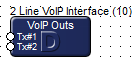
VoIP Transmit #1 and VoIP Transmit #2 input channels are available for the transmission of audio from the Edge or Radius AEC unit to the far end caller.
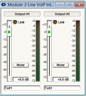
Tx#1 and Tx#2 Label - User editable fields for both output channels.
Transmit Gain Meter, Fader, and Mute button – This meter is calibrated in dBFS from -72dBFS to +0dBFS. The meter will indicate the level of the outgoing signal. The gain fader and its associated Mute button control outgoing signals.
Web Admin Settings Interface
The fields in Web Admin Settings Interface are explained below.
Default Login
Username: Admin
Password: Password
Home
*Network Status*
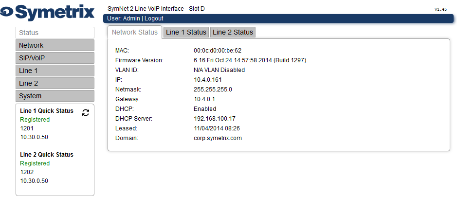
*Card Name* -** Name of the VoIP Card and in which card slot it's seated. (In the DSP host unit).
MAC - MAC Address of the VoIP Card.
Firmware Version - Displays the date the firmware was built and the firmware build version.
VLAN ID - Displays the VLAN ID. Displays 0 if there is no VLAN.
IP - IP Address of the VoIP Card.
Netmask - Subnet Mask of the VoIP Card.
Gateway - Default Gateway of the VoIP Card.
DHCP - Displays if the Dynamic Host Configuration Protocol is enabled or disabled. DHCP will be enabled unless a Static IP address has been assigned.
DHCP Server - Displays the address of the DHCP Server.
Leased - Displays the timestamp of when the IP address was obtained via DHCP.
Domain - Displays the domain handed out by DHCP.
*Line 1 / Line 2 Status*
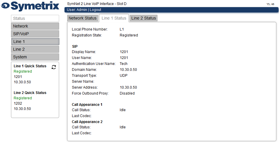
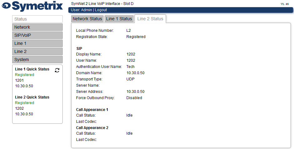
Local Phone Number - Displays the user configurable local phone number.
Registration State - Displays if the card is Registered or Unregistered.
Display Name - Displays the Line Display Name.
User Name - Displays the Line User Name.
Authentication User Name - Displays the Line Authentication Name.
Domain Name - Displays the Line Domain Name.
Transport Type - Displays if the Transport Type is UDP or TCP.
Server Name - Displays the Line Server Name.
Server Address - Displays the Line Server Address.
Force Outbound Proxy - Displays whether Force Outbound Proxy is enabled or disabled.
Call Status - Displays the Call Status (Idle, Ringing, etc.).
Last Codec - Displays which Codec is currently being used or, if not in a call, which codec was last used.
Network
*Basic*
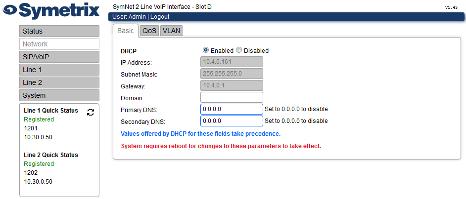
DHCP - Select a radio button to Enable or Disable the Dynamic Host Configuration Protocol for automatic local IP address configuration. If this feature is enabled, you will not be able to set a static IP address to the VoIP Card. By default it is enabled.
IP Address - Set a static IP address to your VoIP Card when DHCP is disabled.
Subnet Mask - Set a static Subnet Mask for your VoIP Card.
Gateway - Set a static Default Gateway IP address for your VoIP Card.
Domain - Set a static Domain for your VoIP Card.
Primary DNS - Set the IP address of the primary domain name server. The default is 0.0.0.0 (Disabled).
Secondary DNS - Set the IP address of the backup domain name. The default is 0.0.0.0 (Disabled).
*QoS*
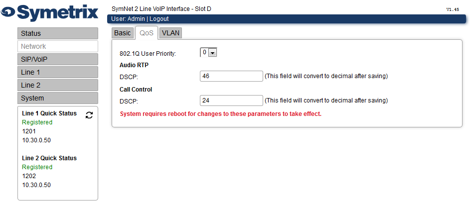
802.1Q User Priority - Set the 802.1Q User Priority from 0-10. This only applies if VLAN is enabled. The default is 0.
Audio RTP IP DSCP - Enter class name, hexadecimal (preceded by ‘0x’) or decimal value. Start typing to see possible values. After saving, the decimal value is displayed. Recommended value is 46 / 0x2e corresponding to EF-PHB.
Call Control IP DSCP - Enter class name, hexadecimal (preceded by ‘0x’) or decimal value. Start typing to see possible values. After saving, the decimal value is displayed. Recommended value is 24 / 0x18 corresponding to CS3.
*VLAN*
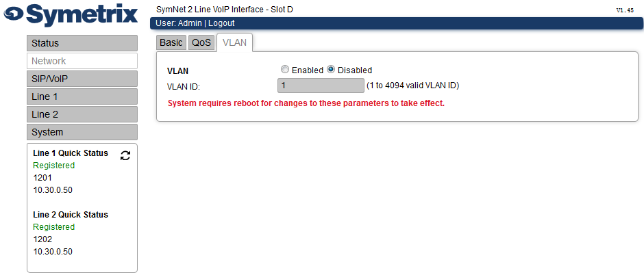
VLAN - Select a radio button to Enable or Disable the VLAN settings. By default it is disabled.
VLAN ID - Set the VLAN ID to be used when the feature is enabled.
SIP/VoIP
*General Settings*
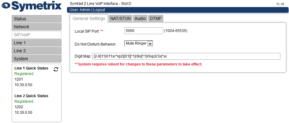
Local SIP Port - Set the local port used for receiving SIP call control messages between 1024 and 65535. The default is 5060.
Do Not Disturb Behavior - Set how the DND button handles a call. The default is “Mute Ringer” which mutes the ringer.
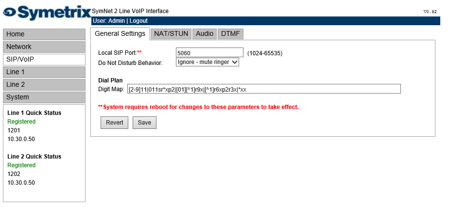
Digit Map - The default map is [2-9]11|011srxp2|[01][1]r9x|[1]r6xp2r3x|xx. For more information on Digit Maps click here.
*NAT/STUN*
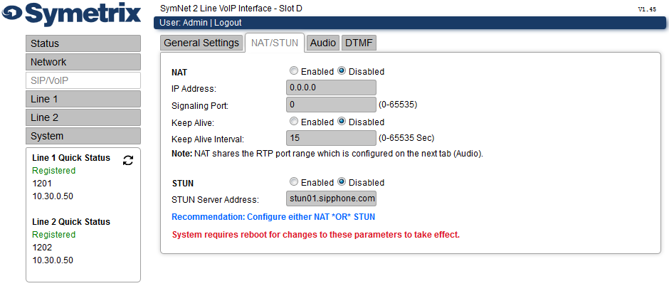
Recommendation: Configure either NAT *"OR"** STUN
NAT - Select a radio button to Enable or Disable the NAT settings. By default it is disabled.
NAT IP Address - Set the IP address of the Network Address Translation router. Set to 0.0.0.0 to disable. The default is 0.0.0.0 (Disabled).
NAT Signaling Port - Set the NAT Signaling Port from 0-65535. The default is 0. Note that changing this value changes the port that the SIP stack listens on.
Keep Alive - Select a radio button to Enable or Disable the Keep Alive function. This function sends periodic SIP messages to keep port mapping active. The default is disabled.
Keep Alive Interval - Set the Keep Alive Interval from 0-65535 seconds. The default is 15 seconds.
“STUN (Simple Traversal of UDP through NATs (Network Address Translation)) is a protocol for assisting devices behind a NAT firewall or router with their packet routing. RFC 5389 redefines the term STUN as 'Session Traversal Utilities for NAT'.
STUN Server - Select a radio button to Enable or Disable the STUN feature. This enables the use of STUN for discovery of NAT. The default is disabled.
STUN Server Address - Enter the STUN Server Address. The default is stun01.sipphone.com (a public STUN server).
*Audio*
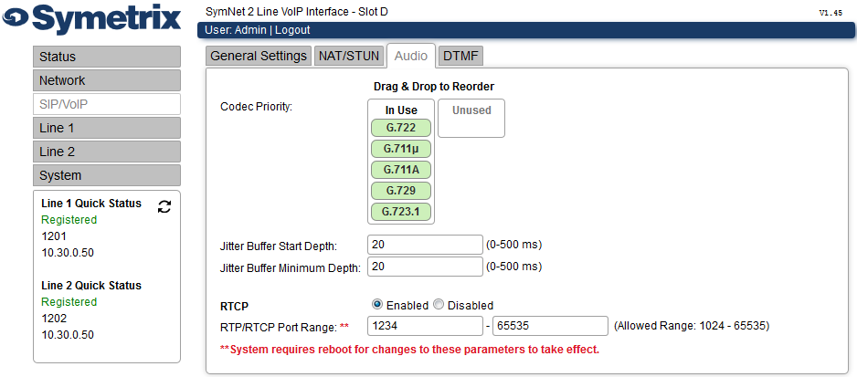
Codec Priority - Drag & drop to set the Audio Codec Priority order and to disable some codecs if required. The default order is G722, G.711 u-law, G.711 A-law, G.729, G.723.1. Note that G.729 Annex B is currently supported for received audio only, the full implementation of VAD for all codecs will be in a future release.
Jitter Buffer Start Depth - Set the Jitter Buffer depth to be used at the start of the call between 0-500 ms. The default is 20 ms.
Jitter Buffer Minimum Depth - Set the Jitter Buffer Minimum Depth between 0-500 ms. The default is 20 ms.
RTCP - Select a radio button to Enable or Disable the RTP Control Protocol. By default it is enabled.
RTP/RTCP Port Range - Set the Real-time Transport Protocol / RTP Control Protocol port range between 1024-65535. The default is 1234-65535. Use an even number for the low end of this range, and an odd number for the high end. For any call, RTP uses an even port number while RTCP uses that number plus one, for example ports 1240 and 1241. The port numbers increase by 2 for every consecutive call until they reach the top of the configured range when they wrap around and begin again. A reboot also resets the port range back to the beginning.
*DTMF*
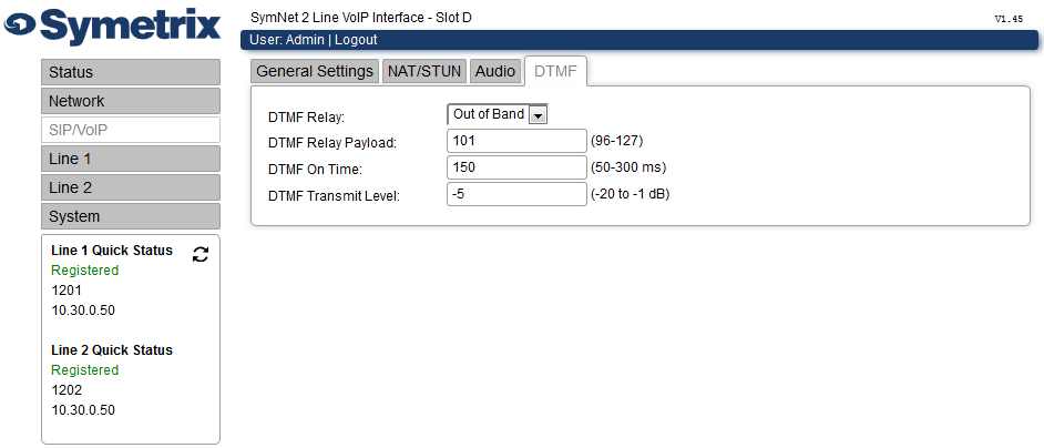
DTMF Relay - Set the Dual-Tone Multi-Frequency Relay to SIP Info, Out of Band (RFC 2833), or In Band. The default is Out of Band.
DTMF Relay Payload - Set the DTMF Relay Payload between 96-127. The default is 101.
DTMF On Time - Set the DTMF On Time between 50-300 ms. The default is 150 ms.
DTMF Transmit Level - Set the DTMF Transmit Level between -20 to -1 dBm. The default is -5 dBm.
Line 1 / Line 2
*Identification*
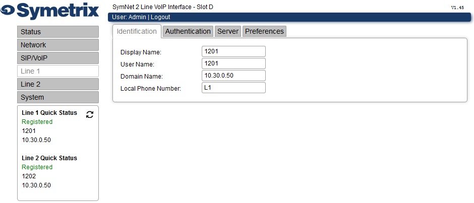
Display Name - Set the name to be used as the Caller ID for the line. Note that the SIP server may ignore this field if it has a Caller ID associated with the registration.
User Name - Set the user name for the SIP registration for this line.
Domain Name - Set the IP address or host name of the SIP server to which the line registers.
Local Phone Number – Set the local phone number of this line, for example X109. This is for informational purposes only and is displayed in the Configuration Settings window.
*Authentication*
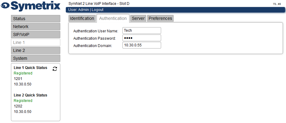
Authentication User Name - Set the user name used for authentication purposes.
Authentication Password – Set the password used for authentication purposes.
Authentication Domain – Set the domain used for authentication purposes. This field must match the authentication realm assigned by the SIP server. It must NOT be translated into any dotted-decimal address equivalent. For some SIP servers, this may be left blank as the SIP messages will convey the authentication domain name to be used.
*Server*
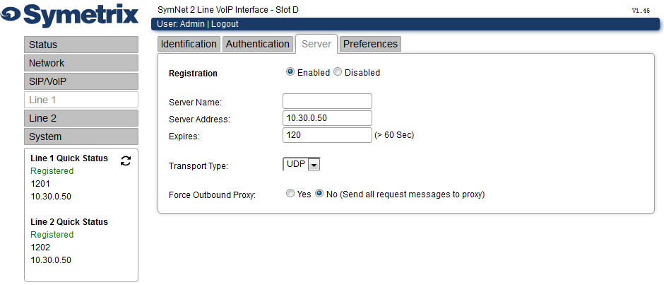
Registration - Select a radio button to Enable or Disable the registration. The default is Enabled. When set to Disabled the line will not attempt to register. It can still be used to place and receive IP-dialed calls.
Server Name - Set the name used to identify the server. This field has no effect on registration.
Server Address - Set the IP address or host name of the server to which registration requests should be sent. This is usually the SIP call server but could be an outbound proxy server too.
Expires - Set the desired registration period in seconds.
Transport Type - Set the transport type used for all SIP messages, either UDP or TCP. The default is UDP. This setting must match the transport type on the SIP server for this registration.
Force Outbound Proxy - Select Yes or No for the Force Outbound Proxy function. The default is No. Select Yes when outgoing requests should be sent to a proxy server which will forward them to the SIP server for this registration. The SIP server is defined in the Domain Name field in the Identification tab, and the proxy server is defined in the Server Address field in this Server tab.
*Preferences*
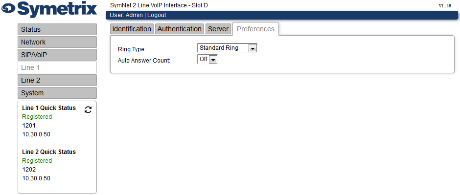
Ring Type - Select the Ring Type from the drop down list. The options are Standard Ring, Double Ring, Stutter Ring, Long UK Ring, UK-style Ring, Internal Ring, Short Single Ring and Silent. The default is Standard Ring.
Auto Answer Count - Select the Auto Answer Count from the drop down list. The options are 0 (Off) – 8. This defines how many rings the card will wait before answering the call automatically. The default is 0 (Off).
System
*Location*
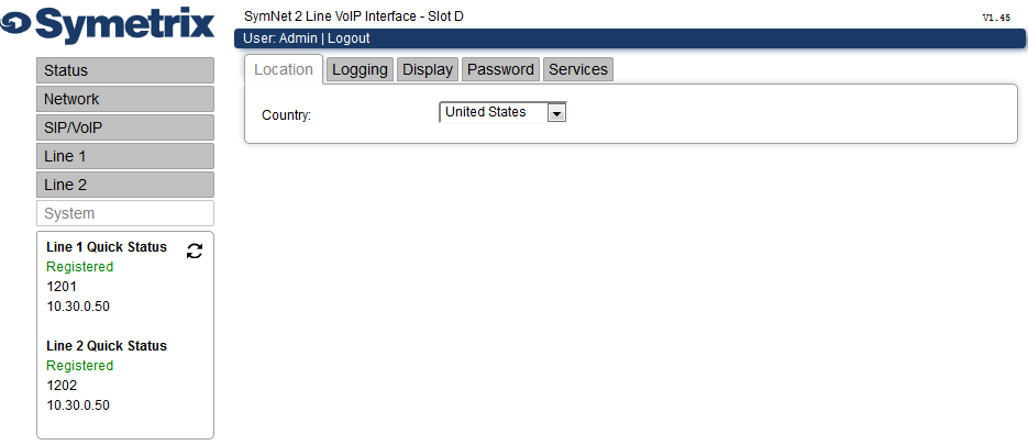
Country - Select your Country from the drop down list. The options are: United States, Australia, Canada, Germany, Japan, Saudi Arabia, and United Kingdom. The default is United States.
*Logging*
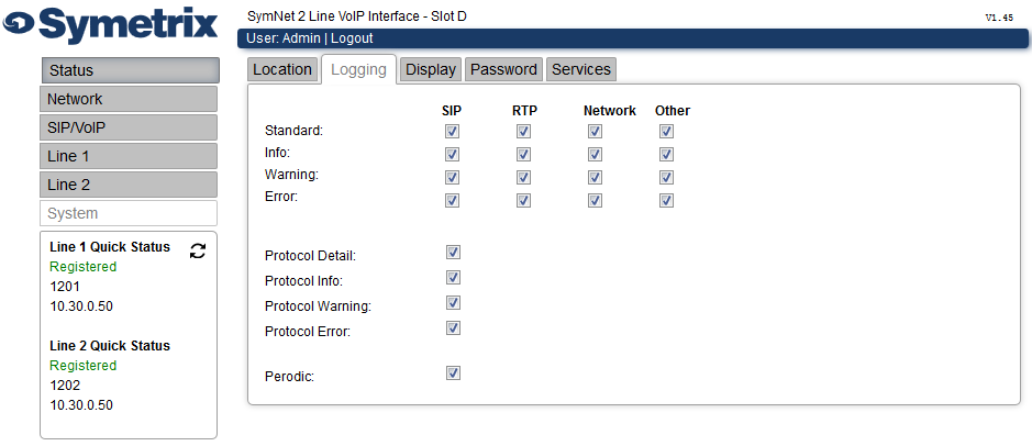
It may be necessary to change Logging settings when troubleshooting a problem. Please contact the Symetrix Support Team for guidance on changing settings.
*Display*
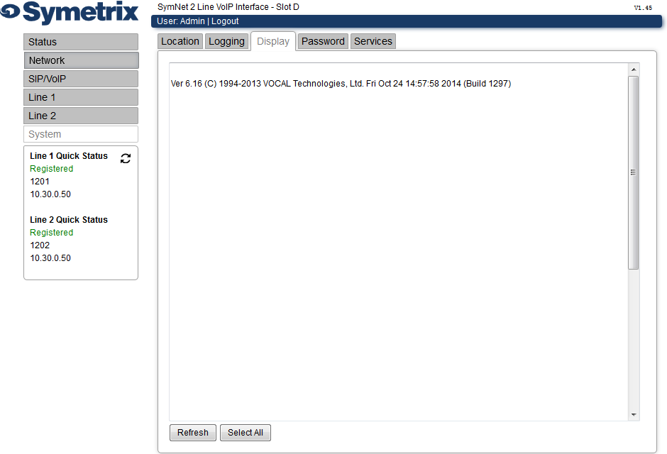
Displays the most recent 250 lines of logging. Click the Refresh button to update the display.
*Passwords*
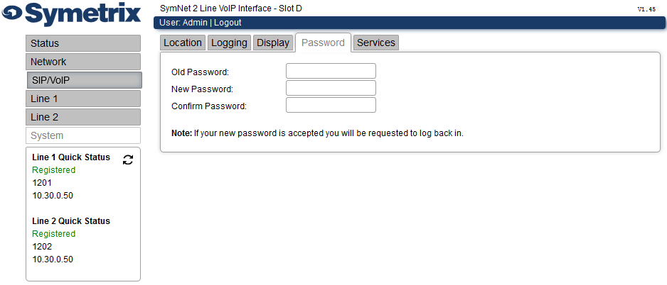
Change the password that is used to log in to the VoIP Web Admin, and Telnet.
Old Password - Enter your old password.
New Password - Enter your new password.
Confirm Password - Enter your new password again to confirm.
After saving the changes you will need to log in again.
Services
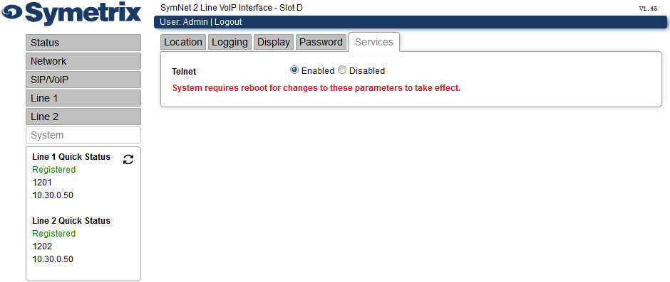
Telnet - Telnet access to the VoIP Card is enabled by default. To improve security, Telnet access can be disabled using this control. It can be re-enabled later if required.
Quick Status
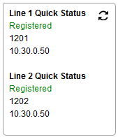
Displays a Quick Status of Line 1 and Line 2 including:
-
If the phone is registered or unregistered.
-
User Name
-
Server Address
Setup Guide
Installing/Running Composer and Upgrading Firmware
Setting up the VoIP card for use with the Cisco Unified Communications Manager
Setting up the VoIP card for Direct IP Dialing (No PBX)
Setting up the Hardware
-
Please see the I/O Card Removal and Replacement portion of our help file for instructions on installing your VoIP Card.
-
Once the card is installed, connect your VoIP card’s RJ-45 port to your VoIP network.
-
Connect your DSP’s RJ-45 port labeled “Ethernet” to your AV network or into a RJ-45 port labeled “Ethernet” on another EDGE or Radius if cascading multiple units.
-
Power the DSP on.
Installing/ Running Composer and Upgrading Firmware
-
Install Composer.
-
Run Composer.
-
A new site file is opened by default.
-
Locate your unit by selecting the checkbox in the bottom left-hand corner of the unit in Site view.
-
Manually upgrade the firmware by selecting the Hardware>Upgrade Firmware/Hardware Settings… Then select the Upgrade… button under Symetrix Microprocessor file, select the most recent version of firmware, and then select the Upgrade button.
-
Select OK.
Supported VoIP PBX
Currently the only supported call platforms are Cisco Unified Call Manager version 9 and above and Asterisk PBX servers.
VoIP cards will only be sold to installations with a Cisco or Asterisk PBX.
No other call platforms are supported and our support teams will not be able to provide assistance for troubleshooting registration or SIP issues outside of the supported platforms.
We will update this page with additional call platforms as they are supported.
Setting up Symetrix 2 Line VoIP Interface for use with Cisco Unified Communications Manager
This guide provides the detailed steps required to both create an account on a CUCM v9.x with the bare minimum required/recommended settings, and to register a Symetrix 2 Line VoIP Interface card to the CUCM.
Navigating to the CUCM
-
Enter the IP address of the server into a browser’s address bar and press Enter (example: 10.30.0.50)
-
Click on Cisco Unified Communications Manager
-
Type in your Username and Password and select Login.
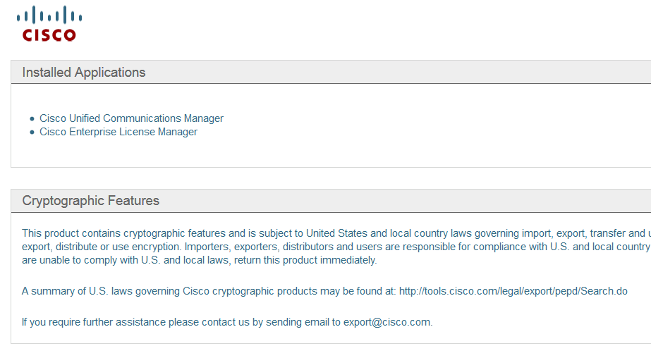
Preparing the CUCM
Note: All fields marked with an ‘’ in CUCM are required for proper setup, some of these fields are set by default*
The steps to create a user account and the related phone information are described next.
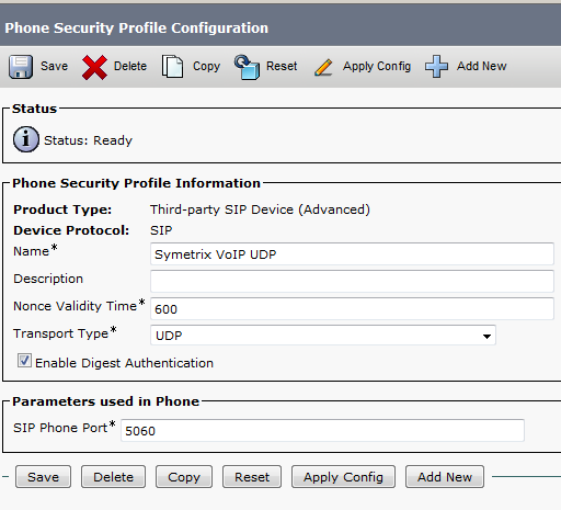
1) Create a Phone Security Profile
a. Select System>Security>Phone Security Profile
b. Click Add New
c. Under Phone Security Profile Type select Third-party SIP Device (Advanced) and select Next (Basic – single line device)
i. Enter the Security Profile Name under “Name*” (Symetrix VoIP UDP, in this example)
ii. Select the desired Transport Type (UDP in this example)
iii. Check Enable Digest Authentication (we recommend using authentication credentials)
d. Click Save
2) Create an End User
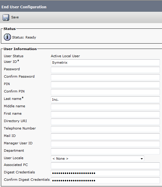
a. Select User Management>>End User
b. Click Add
i. Create User ID (Symetrix, in this example)
ii. Last Name (Inc. in this example)
iii. Digest Credentials (used for authentication) (12345 in this example)
c. Click Save
3) Create a Phone
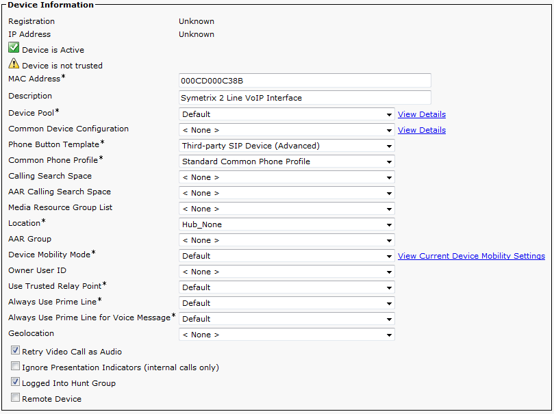
a. Select Device>Phone
b. Click Add New
c. From Phone Type, Select Third-party SIP Device (Advanced) and then click Next
d. Device Information box
i. Enter the MAC Address of the Symetrix 2 Line VoIP Interface card, and description (optional, will default to SEP+MAC Address if left blank)
ii. Device Pool = Default
iii. Phone Button Template = Third-party SIP Device (Advanced)
Note: If only a single line registration is required, we may be able to support the Third-party SIP Device (Basic) option.
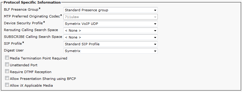
e. Protocol Specific Information box
i. Device Security Profile = Name of security profile created in step 1)
ii. SIP Profile = Standard SIP Profile
iii. Digest User = End User Created in step 2)
f. Click Save
4) Setup Directory Numbers (DN) for the device (this is the extension number)
a. Click on Line [1] – Add a new DN link on left of page
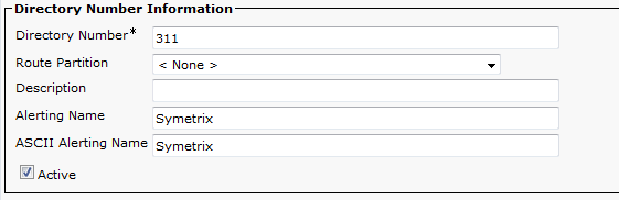
b. Directory Number Information box
i. Enter a Directory Number (311 in this example)
ii. Enter an Alerting Name (Note: ASCII Alerting Name field will auto fill when this is entered)
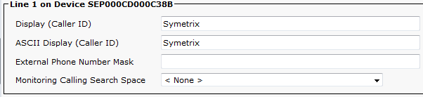
c. Line 1 on Device (description given previously) box (Optional)
i. Enter Display (Caller ID) (Note: ASCII Display (Caller ID) field will auto fill when this is entered)
d. Click Save
e. Click GO next to “Related Links: Configure Device (description given previously) to return to the Phone Configuration page
f. Click on Line [2] – Add a new DN link and follow steps b through e above to register the second line on the Symetrix 2 Line VoIP Interface card.
g. Click Save
Registering the Symetrix 2 Line VoIP Interface
Now that the Cisco CUCM is ready for the Symetrix 2 Line VoIP Interface card, it is time to put the appropriate CUCM credentials into the VoIP Web Admin tool.
1) Setting up Line 1
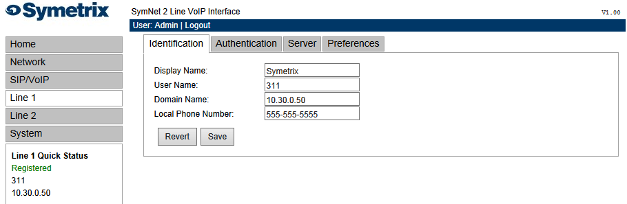
a. Identification tab
i. Display Name (any display name you want)
ii. User Name (this will be the Directory Number for one of the lines created in CUCM, 311 in this example)
iii. Domain Name (server IP address, 10.30.0.50 in this example)
iv. Local Phone Number (this is the number which a far end would dial to call the card)
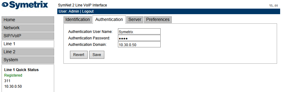
b. Authentication tab
i. Authentication User Name = this will be the End User created in CUCM that the Phone was associated with (Symetrix in this example)
ii. Authentication Password = this will be the Digest Credentials entered for the End User created in CUCM (12345 in this example)
iii. Authentication Domain (typically the same address as the CUCM, 10.30.0.50 in this example)
c. Server tab
i. Server Name
ii. Server Address (this is the address of the CUCM)
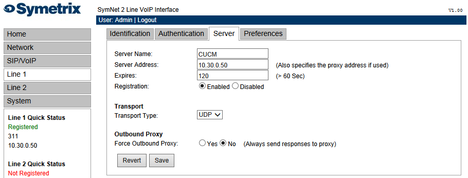
*To set up Line 2 follow the same steps as Line 1, but the User Name will be the Directory Number created for the second line of the device in CUCM
Setting up the VoIP card for Direct IP Dialing
If you do not wish to register your VoIP card to a PBX, you can still direct dial IP addresses. This is mainly used for intercom, paging station testing purposes, or for testing a system before the PBX line registration information is available.
Dialing from the VoIP card to another device
To dial another device using direct IP dialing, you will need to know its IP address. For example, on a Polycom phone, press the Menu button then navigate to Status, Network, TCP/IP Parameters and look for the “IP” address.
The diagram shows an example of dialing from the VoIP card to a far end device that has the IP address 10.4.0.172.
.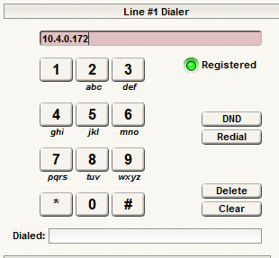
Select the Call/End button to place the call.
Dialing from another device to the VoIP card
To dial the VoIP card from a far end device using IP dialing, you will need to know the IP address of the VoIP card. While in Composer, double click the VoIP Ins module. Select the Configuration Settings... button. Under the VoIP Network settings you will see the IP address. Enter this address as the destination when dialing from the far end. For example, on a Polycom phone which is not registered to a SIP call server, lift the handset then enter the VoIP card’s IP address using the keypad with the ‘*’ key acting as a dot, then press the “Send” soft key. On some Polycom phones which are registered, there is a soft key option called “URL” which is available after lifting the handset which can be used in the same way.
Web Admin Settings
-
While in Composer, double click the VoIP Ins module.
-
Select the Configuration Settings... button.
-
Select the Launch through VoIP Network … button (or, if your VoIP network is completely different from your AV network, select the Launch through AV Network… button).
-
Login: Admin
-
Password: Password
Network Settings
-
Select Network.
-
Select the Basic Tab.
-
By default DHCP is enabled. If a static IP address is required, set it using this page then save the settings and power-cycle the system by unplugging the unit and plugging it back in.
-
Select the VLAN Tab.
-
By default VLAN is disabled. If the card is on a VLAN, enable VLAN and enter the VLAN ID using this page then save the settings and reboot the system by unplugging the unit and plugging it back in.
Line Registration
-
Select Line 1.
-
Select Identification Tab.
-
Display Name: Enter the display name to be used as the default transmitted Caller ID information.
-
User Name: Enter the user name used to register with the SIP server.
-
Domain Name: Enter the SIP Server address.
-
Local Phone Number: Enter the phone number or extension of this registration.
-
Select Save.
-
Select the Authentication Tab.
-
Authentication User Name: Enter the user name used to authenticate this registration.
-
Authentication Password: Enter the password used to authenticate this registration.
-
Authentication Domain: Enter the domain name of the authentication server (this is usually the same as the SIP server name and is only used if the server does not provide a "realm" parameter when it requests user credentials).
-
Select Save.
-
Select the Server Tab.
-
Server Name: Enter a name used locally to identify the server.
-
Server Address: Enter the SIP server address. This field is required. If the “Force Outbound Proxy” option is enabled, this is the address of the outbound proxy.
-
Select Save.
-
Set up the same information for line 2 and make sure to save your settings.
To confirm the lines are registered:
The registration status is displayed in the Quick Status window on the left of the Web Admin tool at all times. The “Registered” LED for each line in the VoIP Ins Module also shows this status. Another option is to do the following:
-
While in Composer, double click the VoIP Ins module
-
Select the Configuration Settings... button
-
Under the Diagnostics sections for Lines 1 and 2, you will see “Registered” next to Registration Status.
*Note** - If you cannot register your lines:
-
Check the SIP Server IP address.
-
Confirm authentication parameters.
-
Make sure you are not using the same settings for both lines.
-
Confirm that you have received all of the Network Settings below in the IT Settings section, from the IT department.
-
Contact Technical Support with the below IT Settings completed.
IT Settings
To efficiently communicate with the IT team when requesting line registration credentials, supply the MAC address of the VoIP interface card along with the fields below to the IT team and request the remaining fields be filled in by the IT team. The default values or examples are shown in bold.
*Network Settings*
Basic
DHCP: ☐Enabled ☐Disabled (Enabled)
IP Address:  0.0.0.0
Subnet Mask: 255.255.255.0
Gateway: 0.0.0.0
Domain:
Primary DNS: 0.0.0.0
Secondary DNS: 0.0.0.0
QoS
802.1Q User Priority: (Only applies if VLAN is enabled) 0
Audio RTP
IP DSCP: (Hexadecimal byte, upper 6 bits are DS field) 46
Call Control
IP DSCP: (Hexadecimal byte, upper 6 bits are DS field) 24
VLAN
VLAN: ☐Enable ☐Disable (Disabled)
VLAN ID: (1 to 4094 valid VLAN ID) 1
SIP/VoIP Settings
General
Local SIP Port: (1024-65535) 5060
Dial Plan
Digit Map: For more information on Digit Maps click here.
Configure Either NAT or STUN Settings
NAT
IP Address: (Set to 0.0.0.0 to disable)
Signaling Port: 0
Keep Alive: ☐Enable ☐Disable (Disabled)
Keep Alive Interval: (15 Sec)
STUN
STUN Server: ☐Enable ☐Disable (Disabled)
STUN Server Address: (stun01.sipphone.com)
Audio
Codecs
Codec Priority: (G.722, G.711 u-LAW, G.711 A-law, G.729, G.723.1)
Jitter Buffer
Jitter Buffer Start Depth: (0-500ms - Must be equal to or greater than the Minimum Depth) 20 ms
Jitter Buffer Minimum Depth: (0-500ms) 20 ms
RTP/RTCP
Port Range: (Allowed Range: 1024 – 65535) 1234-65535
RTCP: ☐ Enable ☐Disable (Enabled)
DTMF
DTMF Relay: (SIP Info, Out of Band, In Band)
DTMF Relay Payload: (96-127) 101
DTMF On Time: (150 ms)
DTMF Transmit Level: (-20 to -1 dBm) -5
Line Settings
VoIP Card MAC Address: 00:0C:D0:
Identification
Line 1 Line 2
Display Name:
User Name:
Domain Name:
Local Phone Number:
Authentication
Authentication User Name:
Authentication Password:
Authentication Domain:
SIP Server Settings
Server Name:
Server Address:
Expires: (120 sec)
Transport
Transport Type Line 1: ☐ UDP ☐ TCP (UDP)
Transport Type Line 2: ☐ UDP ☐ TCP (UDP)
Outbound Proxy
Force Outbound Proxy Line 1: ☐ Yes ☐ No (Always send responses to proxy) No
Force Outbound Proxy Line 2: ☐ Yes ☐ No (Always send responses to proxy) No
Digit Map
The Digit Map (also called the Dial Plan) defines a collection of digit pattern templates that are used to match valid dial strings, for example 7-digit or 10-digit dialing, as the user enters digits. Once a pattern has been matched, the call is placed using the digits that have been entered. These patterns are used to make it easy for an end-user to dial the requisite digits including internal extensions, emergency numbers and external numbers and have the system dial automatically once the proper number and type of digits have been entered. If a user inputs a string of digits that does not match any of the patterns in the dial string the input will be halted and the user will receive an “Input Error” accompanied by the “Busy” LED blinking. If the dial string input by the user matches a pattern but does not complete it and the system has not received input before the timeout has been reached, the default action will be to dial the partial match. This behavior can be changed by adding an “f” to the beginning of the entire pattern template, which causes it to fail on timeout instead of dial. The digit map has no effect when digits are dialed while the phone is on-hook and then taken off-hook because taking the phone off-hook tells the system to dial the digits that have been entered.
The Digit Map is configured using the VoIP Web Admin tool. This tool is accessed either by clicking either one of the “Launch Web Admin” buttons from the Configuration Settings window accessible from the VoIP GUI, or by browsing to the address
The digit map is defined once per system and affects both line registrations.
A quick reference of possible parameters can be accessed by placing the pointer of the mouse over the Digit Map field.
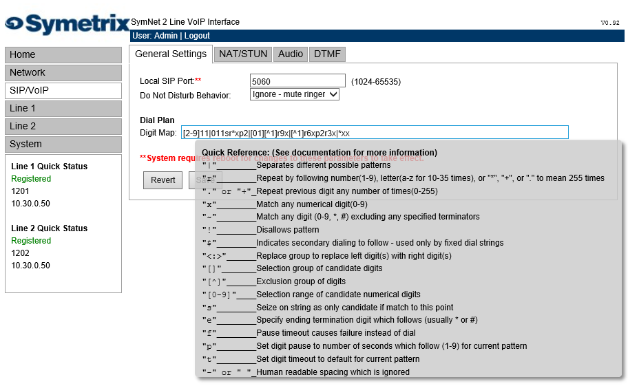
The following table provides a quick summary for all possible Digit Map parameter values.
| Parameter | Description |
|---|---|
| “|” | Separates different possible patterns |
| "r" | Repeat by following number (1-9), letter (a-z for 10 to 35 times) or "*", “+” or "." to mean 255 times |
| "." or “+” | Repeat previous digit any number of times (0 to 255) |
| "x" | Match any numerical digit (0-9) |
| “q” | Discount pattern as possible match if more digits are input (suffix), (if an additional digit is pressed outside of the scope of the preceding pattern, disqualify that string as a possible match and look for another match elsewhere) |
| "~" | Match any digit (0-9, A-D, *, #) excluding any specified terminators |
| "!" | Disallows pattern (suffix) |
| "$" | Indicates secondary dialing to follow - used only by fixed dial strings |
| "<:>" | Replace group, replace left digit(s) with right digit(s) |
| "[]" | Selection group of candidate digits |
| "[^]" | Exclusion group of digits |
| "[0-9]" | Selection range of candidate numerical digits |
| "[a-d]" | Selection range of candidate letter digits |
| "s" | Seize on string as only candidate if match to this point |
| "e" | Specify ending termination digit which follows (usually * or #) |
| "f" | Pause timeout causes failure instead of dial (prefix) |
| "p" | Set digit pause to number of seconds which follow (1-9) for current pattern |
| "t" | Set digit timeout to default for current pattern |
| "-" or “ “ | Human readable spacing which is ignored |
Each of the above parameters, when not used as an informational character, will represent a single digit. This includes if the parameter uses multiple characters for informational reasons.
Below is a detailed view of the default Digit Map:
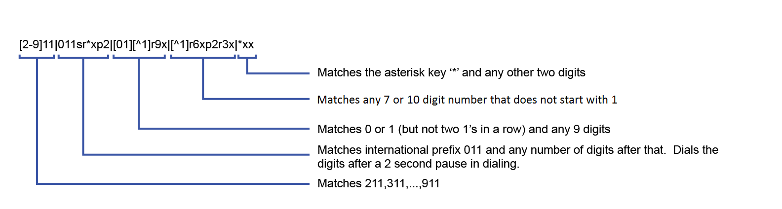
The following examples show how individual patterns are matched:
[3469]11
Allow 311,411, 611 and 911
Each of the items represented in the [] are seen as a single digit. This means “3 or 4 or 6 or 9” plus “11”
1900r7x!
Disallow a 1-900-XXX-XXXX number
This will tell the system to look at the first four digits of the entered number, and if they match “1900” drop to a failed tone.
976r4x!
Disallow a 976-XXXX number
This will tell the system to look at the first three digits of the entered number, and if they match “976” drop to a failed tone.
1800r7x
Allow a 1-800-XXX-XXXX number
This will tell the system to look at the first four digits of the entered number, and if they match “1800” dial using 1800 plus the remaining seven digits.
[^1]r6x
Allow a seven digit number not starting with 1, (2XX-XXXX – 9XX-XXXX)
This will tell the system to look at the first digit, if it is a “1” discount the input as a possible match. However if the string starts with any number between “2-9”, then dial using that digit plus the remaining 6 digits.
11[02]Allow 110 and 112
This tells the system to match the digits “11” and either “0” or “2”. For German emergency services, 110 is the Police and 112 is the Fire Brigade.
Some examples for various extensions:
· “4xxq” – Matches 3 digit extension beginning with ”4”
· “4xxxq” – Matches 4 digit extension beginning with ”4”
· “4r4xq” – Matches 5 digit extension beginning with ”4”
· “4xxp1xq” – Matches 3 and 4 digit extension beginning with ”4”
· “4xxp1xp1xq” – Matches 3, 4, and 5 digit extension beginning with ”4”
The final “q” in the above strings tells the system that if an additional digit is pressed outside of the scope of the preceding pattern, disqualify that string as a possible match and look for another match elsewhere.
0Se#ep2rx
This pattern tells the system to match a “0”, then after pushing a “*” or “#”, allow the user to enter in as many digits as the system can handle, then dial the entire string.
To set up a dial pattern that would allow the user to easily dial between two services, use the <:> symbol. By putting <[89]:> as part of the dial pattern, the system will replace an ”8” or ”9” with a null value, and continue pattern matching as necessary. For example: “<[89]:>r7x”, as long as the first digit is an ”8” or nine ”9”, this pattern will take the set of numbers, remove the first number, and dial out using the remaining seven digits. The user can then put an ”8” as part of the pattern recognition string for one provider, and ”9” as part of the pattern recognition for another provider. This will allow users to easily dial between providers with similar numbers.
If one enters two different patterns which could be easily confused, the system will choose the first pattern that is matched. For example, if two patterns, one for eleven digits followed by one for twelve digits, the system will not wait for the twelfth digit, as it will match to the eleven digit pattern first.
Troubleshooting
-
Auto Answer Count is ignored when Ring type 7 & 8 are selected from the Web Administration Page under Line 1 (or Line 2) >Preferences. The call is immediately answered instead of after the set number of “rings”.
-
URI dialing can only be done on hook. This also applies to redialing a URI.
-
Telnet uses ports 61001-61004 depending on the slot number of the VoIP card. See Port Numbers for more information.
-
Do not specify an RTP port range that includes port numbers reserved for standard purposes. For example, the default port range should not include ports 5060 and 5061 since these ports are used for SIP signaling.
-
Enter only digits in speed dial and direct dial fields when entering phone numbers. For example 5555555555 instead of (555) 555-5555.
-
Set the Jitter Buffer Start Depth to be equal to or greater than the Jitter Buffer Minimum Depth. Note that a larger Minimum Depth will add delay.
-
Turning on high levels of logging may impact system performance. Only increase logging when directed to do so by Symetrix Technical Support.
-
Web Admin performance through the AV Network is slower, use the VoIP Network path when possible.
-
NAT media port range: The range of ports which will be used is configured on the SIP/VoIP – Audio tab for the RTP/RTCP Port Range. Ensure that the range is at least 8 to allow for the four call appearances and two ports per call (RTP and RTCP), for example “1240 – 1247”.
Logging Instructions
A snapshot of recent log messages can be seen in the System – Display page in the Web Admin. Press the “Refresh” button to update the display.
To troubleshoot an issue in consultation with Symetrix support staff, continuous logging may be necessary. For this, a Telnet session can be opened and recorded.
-
While in Composer, double click the 2 Channel VoIP (SIP) Network Interface VoIP Ins module
-
Select the "Configuration Settings..." button
-
The IP address of the VoIP card is displayed in the “IP” field under “VoIP Network”.
-
Open a Telnet session using a program such as TeraTerm or Putty, using the port number from the table below.
Port Numbers
| Card Slot | Telnet Ports | Web Admin Ports |
|---|---|---|
| A | 61001 | 60001 |
| B | 61002 | 60002 |
| C | 61003 | 60003 |
| D | 61004 | 60004 |
User Name: Admin
*Default Password: Password
To turn on logging in the Telnet session, enter “console force”.
*This password is the same as the password to log into the VoIP Web Admin, and can be changed on the System - Passwords page.
To change the logging levels of different modules in consultation with Symetrix support staff, use the check boxes in the System – Logging page in the Web Admin. Note that high levels of logging could affect the performance of the VoIP card.