Symetrix 4 Channel Analog Output
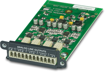 A single Edge frame has four configurable card slots, providing up to 16 channels of local IO. The analog output card provides four channels of line level output. The outputs are electronically balanced and provided on plug-in barrier strip connectors. Control of each output includes gain with metering and mute.
Features:
-
Line output card. Up to 4 cards per frame.
-
+24 dBu maximum output level.
-
+12 dB to off of gain.
-
Extended dynamic range of 117 dB.
-
Field swappable by certified technicians.
Specifications
Number of Outputs: Four (4) balanced line level.
Connectors: 3.81mm terminal blocks.
Nominal Output Level: +4 dBu with 20 dB of headroom.
Maximum Output Level: +24 dBu (+22.8 dBu into a 2k Ohm minimum load).
Output Impedance: 300 Ohms balanced, 150 Ohms unbalanced.
Dynamic Range: > 117 dB, A-weighted.
THD + Noise: < -95 dB, unweighted; 1 kHz @ +22 dBu with 0 dB gain.
Latency: 0.60 mS
Mechanical Data
Shipping Weight: 1 lbs. (0.45 kg)
Certifications or Compliance: EN 55103-1, EN 55103-2, FCC Part 15, RoHS.
A&E Specifications
The device shall provide four analog line outputs to an EDGE frame that are adjustable with fine trim. Up to four of these devices may be installed in a single EDGE frame for up to sixteen channels of local output. Levels and mutes shall be controllable via software. Audio outputs shall be accessed via rear panel 3.81 mm terminal block connectors.
Audio conversion shall be 24-bit, 48 kHz. The dynamic range shall not be lower than 117 dB, A-weighted with a maximum output level of +24 dBu.
The device shall comply with CE and FCC Part 15 emissions limits. The device shall be RoHS compliant. The mounting plate shall be constructed of cold rolled steel, and mount into a Symetrix EDGE frame I/O card slot. The device shall be aSymetrix Symetrix EDGE 4 Channel Analog Output Card.
Connections
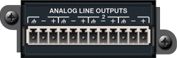 Using standard mic/line cables terminated on one end with terminal block connectors and appropriate connectors for your destination devices on the other end, connect the terminal block ends into the Analog Line Outputs on the card and the opposite ends into your destination devices’ inputs. These outputs are +4 dBu balanced line level outputs by default. If you need an unbalanced output, see the analog audio wiring diagrams in the Audio Wiring Reference.
NOTE: Wiring the outputs to an unbalanced cable will typically result in an output level that is 6 dB lower than the output level achieved using a balanced cable. If wiring to an unbalanced destination, you may need to change the output level. Refer to Composer Controls in the following section.
Composer Controls
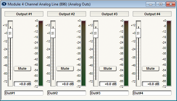
Channel Name (static label): Displays the input channel number.
Gain (fader): Adjusts the gain of the signal in the digital domain. This gain stage is before the digital-to-analog converter. It provides fine gain control between +12 dB to Off in 0.1 dB steps and can be used to optimize signal levels and headroom. Set this according to the signal level expected by the downstream device.
Mute (button): When depressed, this channel will be muted. The muting happens in the digital domain before the digital to analog converter.
Channel Label (user-editable field): Double-clicking in this field allows direct text entry of a user-specified label for the channel.
Meter (bar graph): Shows the level output from the Analog Outs module (post Gain and Mute).