CLOCKAUDIO
A CLOCKAUDIO CDT100, CDT100 Mk II, and CDT3 can be placed in the Site View from the Toolkit.
CDT100 Mk II/CDT3 RGB Configuration
Firmware
The CDT100/100 Mk II ships with UDP firmware loaded from the factory by default. To interface with Symetrix units, you will need to update the firmware to ConMon. Please contact CLOCKAUDIO for the files and instructions at http://clockaudio.com/.
Site View
A CLOCKAUDIO CDT100 can be added to the site view.

Click here for instructions on assigning Dante buses.
Unit Properties
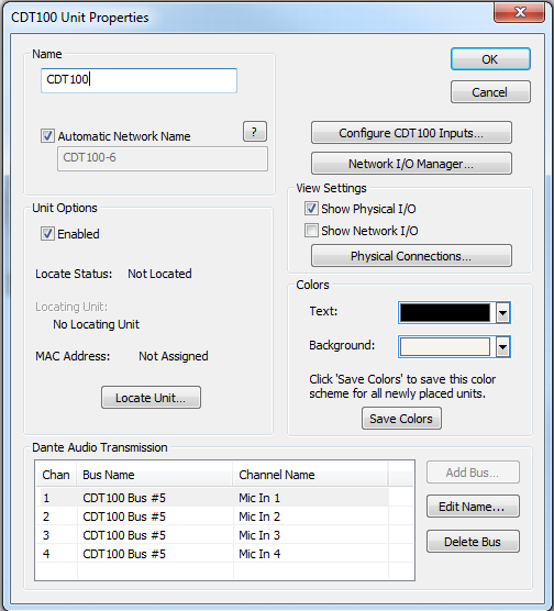
All of the following features are managed in the Unit Properties dialog. To access the Unit Properties, right-click on the unit module in the Site View and choose “Unit Properties...”
-
Name - It is recommended to assign a unique unit name for each unit in the design based on the unit's purpose or location. Composer will always append a unique numeric identifier to this name.
-
Network Name - When Automatic Network Name is checked, the network name is auto-generated from the unit name. Network names cannot contain special characters or spaces and must be unique.
-
Enabled - When the enabled box is checked, the unit must be physically present on the network for a Push of the site file to the hardware. When the enabled box is unchecked, a X will appear on the unit module in the Site View, and the unit will not be required to be physically present for the Push of the site file.
-
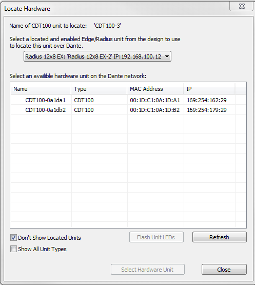
Locate Unit...- Opens the 'Locate Hardware' dialog box to select the unit to connect to.
-
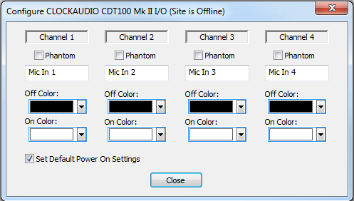
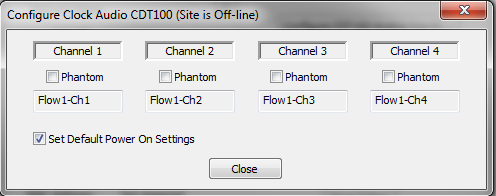
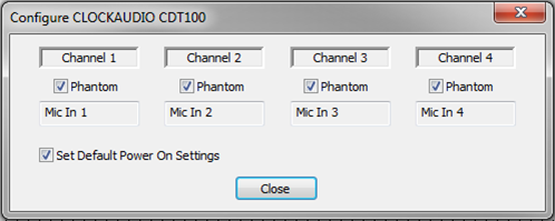
Configure CDT100 Analog Inputs -Configure the phantom power and Default Power On settings of the unit inputs here.
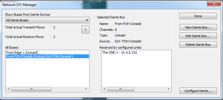
- Network I/O Manager -Opens the Network I/O Manager dialog. Click here for instructions on how to program Network Transmit and Receive Buses.
-
View Settings- When either Show Physical I/O or Show Network I/O check box is checked, the unit module in the Site View will show the corresponding connections.
-
Physical Connections...- Opens the Edit Physical Connections dialog.
- Colors-The text color and background color for the unit module can be customized. To save custom color settings made here as defaults for future units, click the Save Colors button.
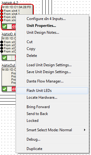
Flash Unit LEDs
Follow these steps to Flash a CDT100's LEDs:
1. Right-click the unit in Site View.
2. Select Flash Unit LEDs
Software Setup
1. Confirm you are running Symetrix Composer 4.1 software or later and that all firmware is up to date.
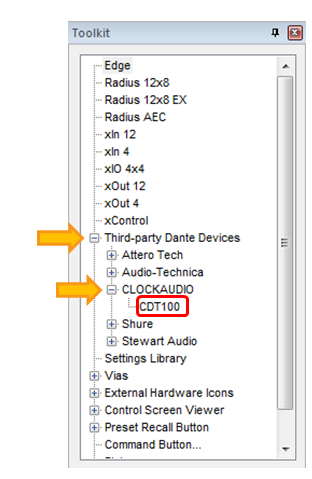
2. Make sure you have a locating DSP in your design then drag a CDT100 from the Toolkit under Third-party Dante Devices>CLOCKAUDIO into Site View...
 3. Locate All units in the site file and click Close.
4. Right-click on the CDT100 in Site View and select Configure CLOCKAUDIO CDT100 Inputs…
5. Check Phantom check boxes if the microphone on that channel requires phantom power and select Close.
6. Double-click the locating DSP to open Design View.
7. From the Toolkit drag in a Dante Receive Flow from the CDT100.
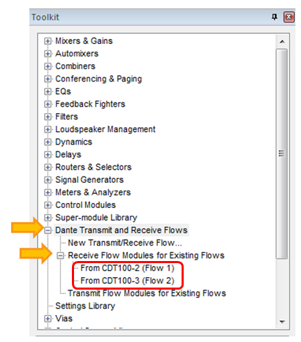
8. Wire the design for the desired signal processing and routing.
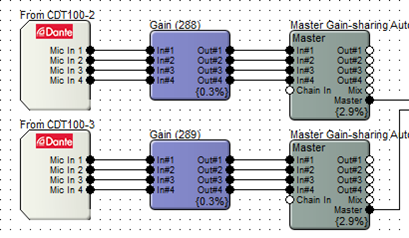
9. Push the site file to archive it to the DSP and go online.
10. Drag in a 4 Button Momentary module from the Toolkit Control Modules>Control Inputs. 11. Drag in a 4-Button Processor Super-module from the Super-module Library>Import super-module.
- With ARM-C use CDT100 Processor or CDT100 Processor wUnmute Delay from the 3rd Party Control folder.
- Without ARM-C use 4-Button Processor from Tools folder.
12. Wire the output of the 4 Button Momentary control module to the input of the 4-Button Processor.
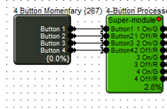
13. Drag in a Remote Logic Output from the Toolkit under Control Modules>Control Outputs.
14. Select CDT100 for Remote Unit.
15. Select Green LED #1 for the Logic Output.
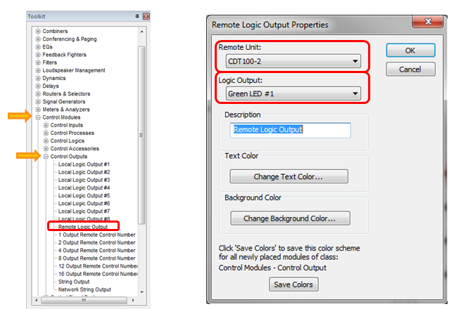
16. Drag in a Remote Logic Output from the Toolkit under Control Modules>Control Outputs.
17. Select CDT100 for Remote Unit.
18. Select Red LED #1 for the Logic Output.
19. Wire the output of the 4-Button Processor (1 On/G) to the Remote Logic Output.
20. Wire the output of the 4-Button Processor (1 Off/R) to the Remote Logic Output.
21. Repeat steps 13-20 for each remaining button.
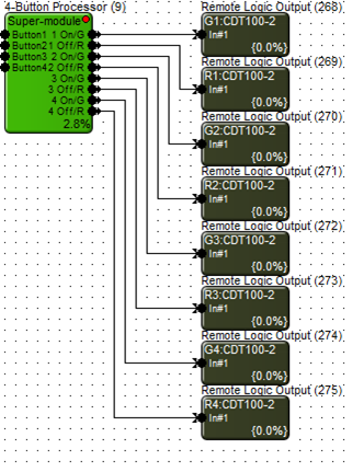
22. When using ARM-C, select ARM-C for the Logic Output in the Remote Logic Output Properties.
23. Wire the output of the 4-Button Processor (ARM-C) to the Remote Logic Output.
24. Double click and open either a Gain Module or Automixer used in the signal processing and routing of the microphones.
25. Right-click on Channel 1 Mute button.
26. Select “Set Up Remote Control...”
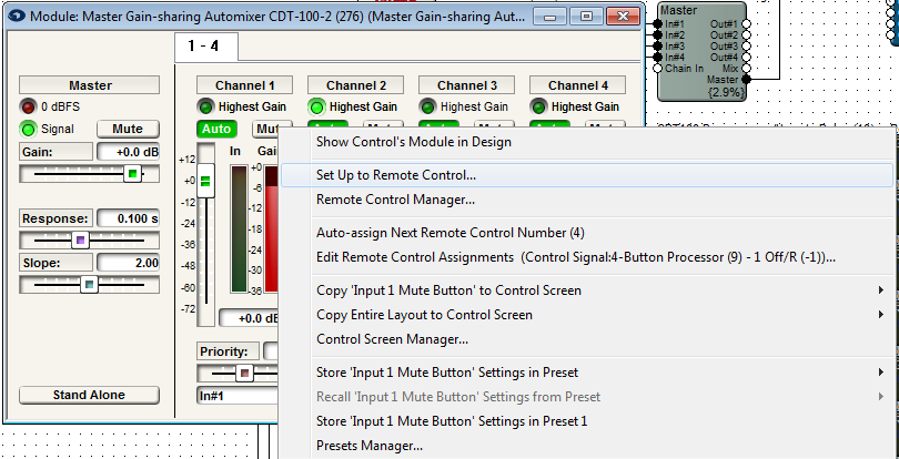
26. Select Control Signal Assignment for the Remote Control Device.
27. Click Select.
28. Expand the 4-Button Processor.
29. Select 1 Off/R.
30. Click OK.
31. Repeat steps 17-23 for each microphone channel. Assigning the Mute button of each microphone channel to its corresponding x Off/R output of the 4-Button Processor.
32. Double-click the 4 Button Momentary module.
33. Right-click the On for Button 1.
34. Select Set Up Remote Control...
35. Select Remote Mic Switch - 'CDT100' for the Remote Control Device.
36. Select Switch #1 for the Select Analog Control.
37. Click OK.
38. Repeat steps 26-30 for each button of the 4 Button Momentary module. Assigning each On button with its corresponding Mic Switch.
39. Double click the 4-Button Processor to open the Super-module control screen.
40. Select the desired microphone switch operation (Push to Talk, Push to Mute, Toggle, or Disabled).
- ARM-C has Radio, Toggle, and Latching controls.
41. Push the site file to go online.
CDT100 Mk II/CDT3 RGB Configuration
The CDT100 Mk II and CDT3 are able to control RGB lighting on other CLOCKAUDIO devices. These settings can be found in the unit's configuration dialog.