Example Site Files
Updating the Example Site File Folder
Symetrix Radius AEC Template Guide
Updating the Example Site File Folder
The example site file folder is installed in the following directory by default:
My Documents>Composer X.x>Designs>examples
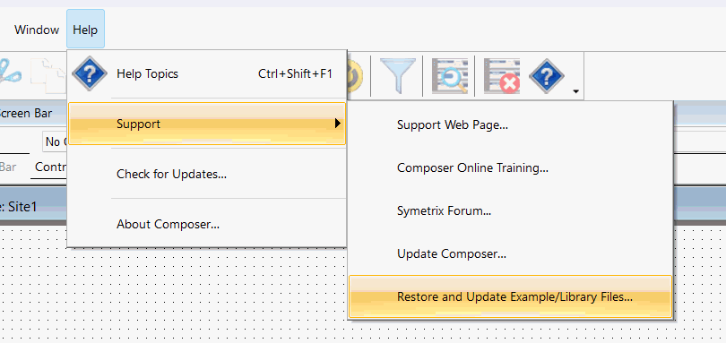
To update or restore the example site files, go to Help>Support>Restore and Update Example Files:
A dialog similar to the following will pop up:
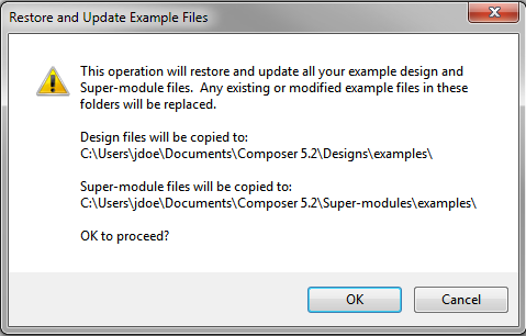
Select OK.
Symetrix Radius AEC Template Guide
System Overview:
The following Symetrix Radius AEC Site File design templates can be used with Symetrix Composer software version 2.50 or higher.
-
8_Mic_RadiusAEC_with_ATI_card_verX.Y.symx
-
20_Mic_RadiusAEC_with_ATI_card_verX.Y.symx
-
32_Mic_RadiusAEC_with_ATI_card_verX.Y.symx
-
8_Mic_RadiusAEC_with_VoIP_card_verX.Y.symx
-
20_Mic_RadiusAEC_with_VoIP_card_verX.Y.symx
-
32_Mic_RadiusAEC_with_VoIP_card_verX.Y.symx
Each of the design templates uses the Symetrix Radius AEC with either a Symetrix 2 Line Analog Telephone Interface (ATI) card or 2
Line VoIP Interface card installed in the option slot. The larger systems add one or more Radius AEC’s with the AEC card installed
in the option slot to add 12 or 24 additional microphones to the 8-microphone project. The templates are designed to work with
a Dante Virtual Sound (DVS) card, and they are set-up to support 1 channel of audio from the diagnostic tool “Selected Wire” and
2 channels of program audio routed from the PC’s DVS card. They will also support 2 input channels and 2 output channels from
the DVS card for a Soft Conferencing Audio/Video codec such as Microsoft Lync, WebEx, Skype or many others.
Detailed below is the Composer software Site File design template system overview:
The Symetrix Radius AEC has 8 microphone inputs, 4 line level inputs and 64 Dante inputs.
- Inputs 1 – 8 can be used for conferencing microphones. Any number of those mics may be reinforced in the local room.
- The option card slot is configured with either the 2 Line Analog Telephone Interface card or 2 Line VoIP Interface card.
- Line Inputs 1 and 2 support an analog stereo Video Conferencing Codec input.
- Line Inputs 3 and 4 support an analog input from a router, switcher or any other analog source for Program Audio.
- Dante Inputs 1 and 2 should receive audio from the DVS channels 1 and 2 for Program Audio.
- Dante Inputs 3 and 4 should receive audio from DVS channels 3 and 4 for the VTC soft codec. You should use channels 3 and 4 because in a Microsoft based PC the PC’s audio mixer adds the default PC audio recording devices to the 1 and 2 channel mix and this may include the PC’s internal mic which will cause echo problems.
The Radius AEC has 8 analog line level outputs and 64 Dante outputs. By default all connections and routing are as follows,
- Outputs 1 and 2 are for the Front Left and Right Loudspeakers. The VTC Receive and Program Audio are routed to these outputs by default but these outputs can support all audio sources.
- Outputs 3 and 4 are for 2 zones of output to the Ceiling Loudspeakers. By default the Front Ceiling zone supports all audio except for the local in-room microphone audio. The Main Ceiling output has all audio for the room including the local in-room microphone audio.
- Outputs 5 and 6 are for a stereo Record Output and by default include all microphones sent to the phone and VTC conferencing outputs, Phone 1 and 2 receive signals, VTC receive audio and program audio.
- Outputs 7 and 8 are all audio being sent to the Video Conference Codec and by default include all microphones sent to the phone, Phone 1 and 2 receive signals, and the program audio. This routing can be changed using the System Router page.
- Dante output 1 is the “Selected Wire” diagnostic audio output to the PC.
- Dante outputs 2 and 3 are to the PC for the VTC soft codec transmit audio. These should use channels 3 and 4 in on the DVS card because in a Microsoft based PC the PC’s audio mixer may add the default PC audio sounds to the 1 and 2 channel mix and this may not be desirable for the far end.
The other configuration files are designed in the same way and differ only in the number of microphones and the number of
devices that are linked together to support that number of microphones.
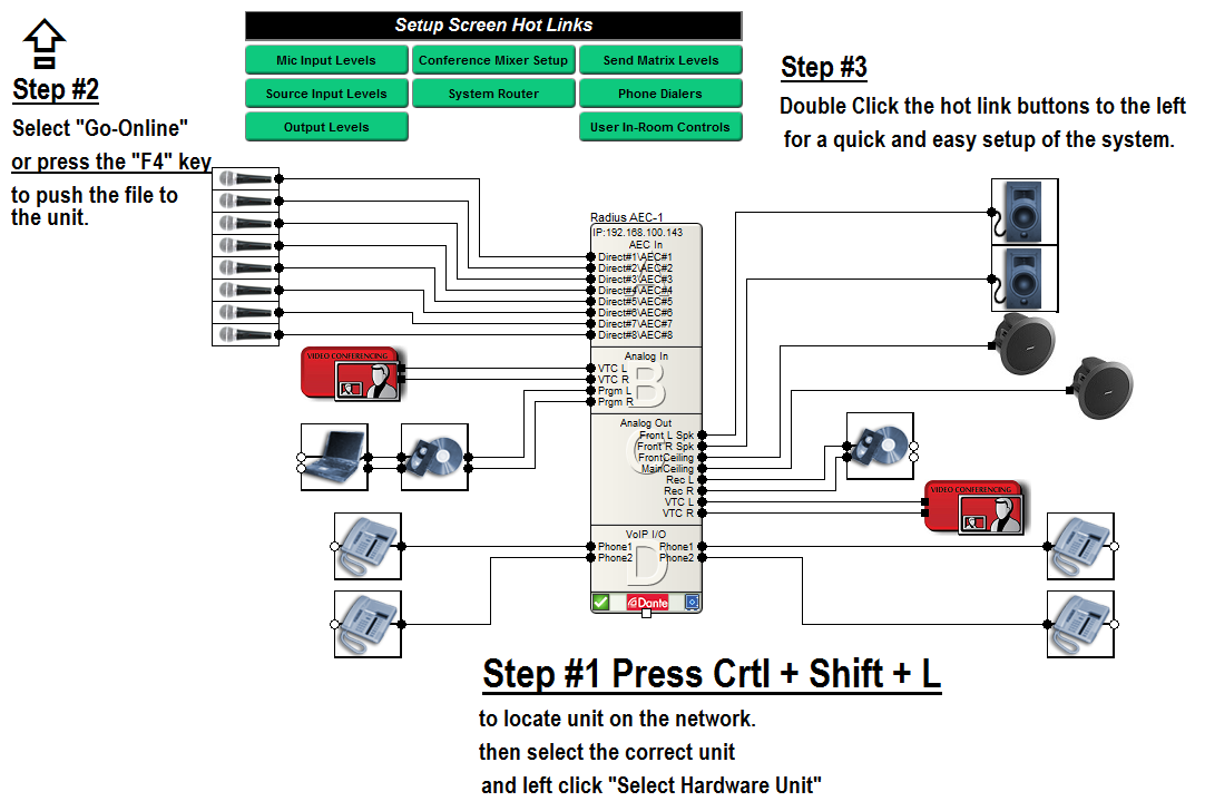
The main page of the template includes Setup Screen Hot Links as shown in the following figure and as described below.
Mic Input Levels and Source Input Levels Pages:
These windows set the input gain for all mics, all analog inputs and all Dante network audio inputs. You can also turn on and
off Phantom Power, Noise Cancellation and adjust the level of Noise Cancellation attenuation for the mics as well as adjust the
basic settings of the Gated Conferencing Mixer. All of these settings are global and apply to all of the mics sent to the Phone
1, 2 and VTC outputs. The Hold Time adjusts how long a mic stays open after a signal which exceeds the gate threshold stops.
The off attenuation is how much attenuation is applied to a mic input when the input signal drops below the noise floor. The
Gate Threshold is how far a signal has to be above the dynamically measure noise floor before a mic will gate on. The NOM
Limit is how many mics will be allowed to gate on at the same time and the “Current NOM” is just showing how many mics
are actually gated on.
Output Levels Setup Screen:
This window allows you to calibrate the analog output levels to match the needed input level for the attached device. Be aware,
all of these levels are being adjusted at the appropriate location but not necessarily at the analog output.
The Front Left and Right loudspeakers, Front Ceiling, Main Ceiling and Record Out are all adjusted in the 8-Ch Analog Output module (1207).
VTC Out is adjusted with a gain control module (1218) inserted upstream from a Comp/Limiter. This is done because Video
Conferencing Codecs generally have less dynamic range than Symetrix Radius AEC. Adjusting gain before the Comp/Limiter will
reduce the likelihood of clipping the transmit signal at the input of the codec. The compressor uses a 10/1 ratio above -6dBFS.
A similar setup is used on the Phone outputs using modules (1217 and 1225) for gain. The Compressor/Limiter helps to limit the
dynamic range to the analog phone lines. The compressor uses a 10/1 ratio above -10dBFS.
Send Matrix Setup Screen:
This window allows you to adjust individual levels to Phone 1, Phone 2, VTC and Record Out at the appropriate crosspoint in
order to balance all signals sent to a particular output without affecting other signal paths.
Phone Dialers Setup Screen:
This window allows you to control the individual Phone Lines and save Speed Dial numbers.
System Router Setup Screen:
This window allows you to route all audio to the desired outputs. The blue boxes indicate the inputs on the left side and the
destinations across the top or to the right. If the button shows “Disconnected” then the audio source noted on the left is not
routed to the destination indicated across the top or on the right.
The matrix on top is for routing input audio to the desired output.
Below this matrix Mics 1 through 8 can be individually routed to the local room as needed. By default no mics are routed to
the room for local reinforcement.
User In-Room Controls Page and 3rd Party Device Controls:
Note: In order to view all Control ID’s preprogrammed into the system press “Alt M” on your keypad and the ID’s will be toggled on
all pages and in the Design View. The “User In-Room Controls” page can also be exported to SymVue in order to be used with a
Windows based touchpanel or PC.
Master Volume:
This controls all audio in the room except for the locally reinforced microphones. Program, Phone 1 and 2 and VTC can be set
relative to each other and this will control them while maintain the relative differences of each.The control ID is 301which
will provide feedback when a change occurs and the suggested range is -35 to +12 and the default starting level is -6dB. It is
controlling Outputs 1, 2, 3, 4 Master Faders in the Room Mixer module (1213).
VTC Volume:
This controls the VTC Receive audio level only in the local room.The control ID is 302which will provide feedback when a
change occurs and the range is -12 to +12 and the default starting level is 0dB. It is controlling the appropriate Gain Faders in
the Room Mixer module (1213).
Program Volume:
This controls the Program audio level only in the local room.The control ID is 303which will provide feedback when a change
occurs and the range is -12 to +12 and the default starting level is 0dB. It is controlling the appropriate 2 Gain Faders in the
Room Mixer module ( 1213).
Phone 1 Volume:
This controls the Phone 1 Receive audio level only in the local room.The control ID is 304which will provide feedback when a
change occurs and the range is -12 to +12 and the default starting level is 0dB. It is controlling the appropriate Gain Faders in
the Room Mixer module (1213).
Phone 1 Dialer
The VoIP phone dialer uses controller ID’s ranging from101 to 139for Line 1. The analog telephony phone dialer users
controller ID’s ranging from101 to 125for Line 1. The speed dials use controller ID’s140 - 159for the VoIP interface and126 to
145for the analog telephony interface.
Phone 2 Volume:
This controls the Phone 2 Receive audio level only in the local room.The control ID is 305which will provide feedback when a change occurs and the range is -12 to +12 and the default starting level is 0dB. It is controlling the appropriate Gain Faders in the Room Mixer module (1213).
Phone 2 Dialer
The VoIP phone dialer uses controller ID’s ranging from401 to 439for Line 2. The analog telephony phone dialer users controller ID’s ranging from 151 to 175 for Line 2. The speed dials use controller ID’s440 - 459for the VoIP interface and176 to 195for the analog telephony interface.
Master Room Mute:
This controls mutes or unmutes all audio in the room except for the locally reinforced microphones. Program, Phone 1 and 2 and VTC receive audio will be muted regardless of which loudspeaker output it is routed to.The control ID is 299which will provide feedback when a change occurs. It is controlling the Mute in the applicable Speaker Manager modules (1210) and (1211).
VTC Mute:
This control mutes or unmutes the VTC Receive audio in the local room and to the other conferencing destinations.The control ID is 260and will provide feedback when a change occurs. It is controlling the appropriate Input Mutes of the 4ch Analog Input module (1202).
Program Mute:
This control mutes or unmutes the Program audio in the local room and to all conferencing destinations.The control ID is 263and will provide feedback when a change occurs. It is controlling the appropriate Input Mutes of the 4ch Analog Input module (1202).
Phone 1 Mute:
This control mutes or unmutes the Phone 1 Receive audio in the local room and to the other conferencing destinations.The control ID is 261and will provide feedback when a change occurs. It is controlling the Telco #1 Receive Mute module and the Phone 1 In Gain mute module.
Phone 2 Mute:
This control mutes or unmutes the Phone 2 Receive audio in the local room and to the other conferencing destinations.The control ID is 262and will provide feedback when a change occurs. It is controlling the Telco #2 Receive Mute module and the Phone 2 In Gain mute module.
Record Out Mute:
This control mutes or unmutes all of the Record audio to the Record Output.The control ID is 269and will provide feedback when a change occurs. It is controlling channel 5 and 6 Output Mutes of the 8ch Analog Output module.
VTC Transmit Mute:
This control mutes or unmutes all of the VTC Transmit audio to the far end.The control ID is 270and will provide feedback when a change occurs. It is controlling channel 7 and 8 Output Mutes of the 8ch Analog Output module.
Phone 1 Transmit Mute:
This control mutes or unmutes all of the Phone 1 Transmit audio to the far end.The control ID is 267and will provide feedback when a change occurs. It is controlling the Telco #1 Output Mute module and the Phone 1 Out Gain mute module.
Phone 2 Transmit Mute:
This control mutes or unmutes all of the Phone 2 Transmit audio to the far end.The control ID is 268and will provide feedback when a change occurs. It is controlling the Telco #2 Output Mute module and the Phone 2 Out Gain mute module.
Privacy Mute On/Off:
This control mutes or unmutes the transmit microphone audio only to all far ends (phone 1, phone 2 and VTC) and to the record output. This does not mute any of the program audio being transmitted to the far end or record output. It also does not mute the microphones being reinforced in the local room.The control ID is 250and will provide feedback when a change occurs. It is controlling the Master Mute of the Master Gating Automixer module in the 8 mic Gated Conferencing Super Module.
Voice Lift On/Off:
This control mutes or unmutes the local in room microphone audio only. It has no effect on the microphone audio to the far end or record outputs.The control ID is 251and will provide feedback when a change occurs. It is controlling the Master Mute of the Room Mics Automixer module in the 8 mic Gain Sharing Local Room Super Module.
Front Speakers On/Off :
This control mutes or unmutes any audio routed to both the left and right front loudspeaker outputs in the local room only. It has no effect on the audio to the far end or record outputs.The control ID is 265and will provide feedback when a change occurs. It is controlling Output 1 and 2 Mutes of the Output Router module.
Ceiling Speakers On/Off:
This control mutes or unmutes any audio routed to both the front and main ceiling loudspeaker outputs in the local room only. It has no effect on the audio to the far end or record outputs.The control ID is 266and will provide feedback when a change occurs. It is controlling Output 3 and 4 Mutes of the Output Router module.
Advanced Control:
Mute control is also provided for the individual microphones in the 8 Ch AEC Inputs block for advanced control applications.Control ID’s 201 through 208are used to individually control the mute of microphone inputs.