RC-3 (Potentiometer) Programming
Configuring External Control Inputs
The Symetrix RC-3's (or any standard 10k Ohm linear taper potentiometers) connect to the External Control Inputs (maximum of one per input) with standard shielded twisted pair wiring shown below:
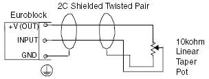
Configuring External Control Inputs
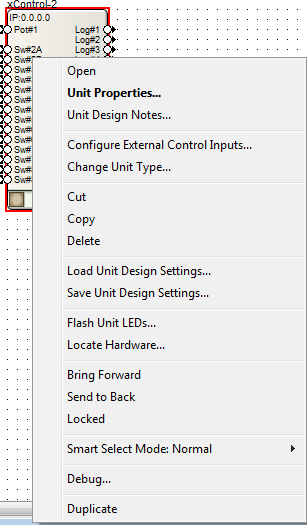
After making the physical connections, configure the External Control Inputs by right-clicking on the xControl in Design View and select "Configure External Control Inputs...":
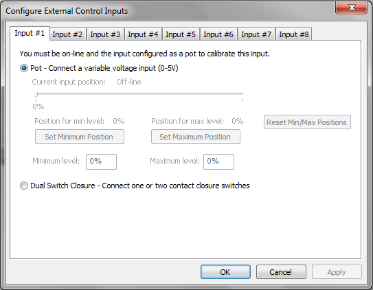
To configure the input for use with a potentiometer, select the appropriate input tab, and then select the "Pot - Connect a variable voltage input (0-5V)" radio button. Select "OK" when finished.
Pot Calibration
Note: You must be on-line and the input configured as a pot to calibrate the input. You must also have the pot physically wired to the External Control Input.
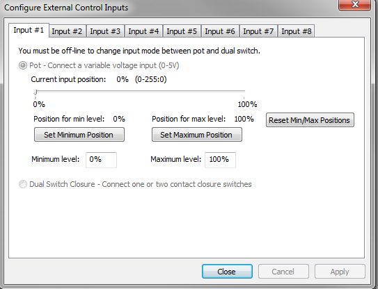
Calibrating the External Control Input determines the way the 0-5V potentiometer affects Composer parameters. There are two separate areas that can be altered:
1. Compensation for pots that don't get all the way down to 0V or all the way up to 5V. This could happen because of characteristics of the pot itself, or resistance in the connection between the pot and the unit, especially with long wire runs. This is referred to as Calibrating Pot Range below.
2. Limiting the range of parameters controlled by an analog input. This is referred to as Calibrating Control Range below.
This setting should match the control input of the pot being calibrated. If a pot is connected and the settings are correct, turning the pot should move the small indicator along the Current input position line. The value of the pot (0-255) is also updated to show the current level generated by the pot. Zero represents GND or 0V, 255 represents 5V, and the range is linear.
Calibrating Pot Range
To compensate for a pot that doesn't travel the entire range, make sure the pot is connected to the one of the 8 analog control input ports and the correct input is selected as described above. Turn the pot to its minimum value (usually all the way counterclockwise). Click the Set Minimum Position button. Next, turn the pot to its maximum value (usually all the way clockwise). Click the Set Maximum Position button.
Note that you can use these settings to compensate for a reverse-wired pot. If you want to reset the calibration, click the Reset Min/Max Positions and they will be returned to their defaults.
Calibrating Control Range
You can limit the range of a Composer control that is being controlled by an analog control input. For example, if a pot is controlling a volume fader, you may only want to allow the fader to go from -30dB to 0dB rather than the full -72dB to +12dB range allowed in the software. To limit the upper range of a control, enter a value less than 100% for the maximum level. To limit the lower range of a control, enter a value greater than 0% for the minimum level. When set to 100% and 0%, the control is allowed to travel the entire range shown in the Composer control screen. Other values reduce this range accordingly. Some experimentation may be required to find the percentage values that limit a range appropriate for your application.
Important Notes:
By setting the minimum value to a number larger than the maximum value, you can reverse the operation of the pot or compensate for a reverse-wired pot. If you want to reset the calibration, enter 100% for the maximum level and 0% for the minimum level.
If you want to reset all analog calibration data for a unit, this can be done using the Erase Memory command found under Hardware->Upgrade Firmware. Select only Analog Calibration Settings and hit ERASE.
All settings made using this dialog box are stored in the hardware, not in the site file. Changes made take effect immediately without the need to download the entire site.
Assigning a Parameter
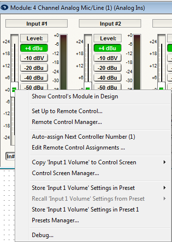
Right-click directly on the parameter and select "Set Up Remote Control."
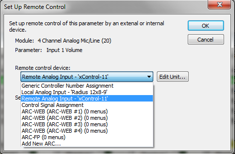
Click the drop down arrow under Remote control device and select "Remote Analog Input - 'xControl'"
Click the drop down arrow under Select Analog Control and choose the pot that matches the physical wiring on the External Control Input. Select OK when finished.
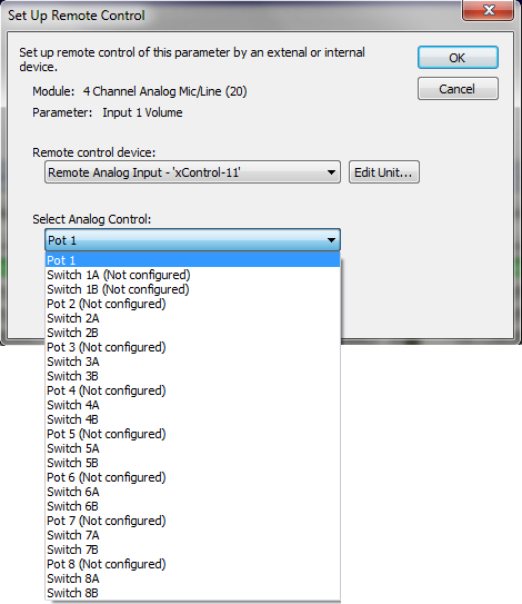
If the input says "(Not Configured)" next to it, the External Control Inputs were not configured first. See Configuring External Control Inputs.
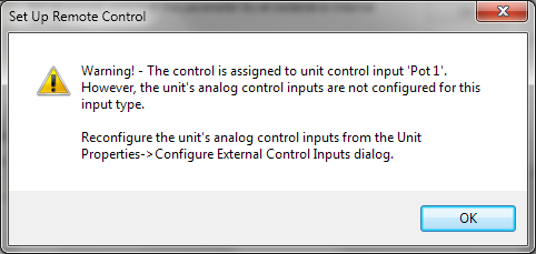
Note: Only one potentiometer can be assigned to a parameter.
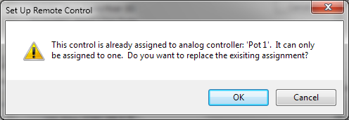
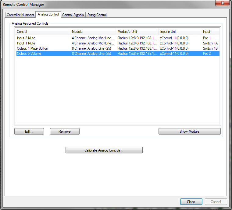
Analog Assigned Controls