Control Outputs
(RS-232/485) Control Number Output
Baud Rate, Deaf Mode and other System Considerations
Local Logic Output modules
These modules provide access to the logic outputs on a Symetrix Edge, Radius DSP, or xControl. These modules allow controlling these outputs from control signals for external display and/or control of other 3rd party devices.
There are separate modules for controlling each of the (8) logic outputs found on Edge and Radius DSP units. These modules allow controlling the logic output contact closure, from a control signal. Programmable thresholds determine the level of the control signal required to turn on the circuit. The threshold is specified in two parts to allow for hysteresis. If the input signal is above both thresholds, then the logic output is on. If the input signal is below both thresholds, then the logic output is off. If the input falls between the thresholds, then the circuit remains at its previous state.
When a logic output is on, it is shorted an not in it's normal state, i.e. the normally open terminals are closed and the normally closed terminals are open. When the logic output is in it's normally off state, the terminals are open and ~ 5vDC is present with respect to ground.
Controls:
-
Off Threshold. Determines the level below which the control signal must fall to turn off the relay. Adjust using the slider or click in the text entry box to specify a numerical value.
-
On Threshold. Determines the level above which the control signal must rise to turn on the relay. Adjust using the slider or click in the text entry box to specify a numerical value.
** Note: If Off Threshold is set higher than On Threshold, the logic output will work in reverse, i.e. it will be off when the **
-
input is above Off Threshold and on when the input is below the On Threshold.*
-
Current State, On button. In manual mode, this button allows controlling the relay manually. When manual mode is off, this displays the current state.
-
Manual. When depressed, the On button is used to control the logic output directly rather than the control signal input. When not depressed, the control signal controls the logic output and the on button is ignored.
A text display is provided showing the level of the input.
Remote Logic Output modules
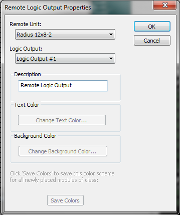
There are separate modules for controlling each of the remote logic outputs found on Edge, Radius DSP, and xControl units. These modules allow controlling the logic output contact closure, from a control signal. Programmable thresholds determine the level of the control signal required to turn on the circuit. The threshold is specified in two parts to allow for hysteresis. If the input signal is above both thresholds, then the logic output is on. If the input signal is below both thresholds, then the logic output is off. If the input falls between the thresholds, then the circuit remains at its previous state.
When a logic output is on, it is shorted an not in it's normal state, i.e. the normally open terminals are closed and the normally closed terminals are open. When the logic output is in it's normally off state, the terminals are open and ~ 5vDC is present with respect to ground.
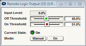
Controls:
-
Off Threshold. Determines the level below which the control signal must fall to turn off the relay. Adjust using the slider or click in the text entry box to specify a numerical value.
-
On Threshold. Determines the level above which the control signal must rise to turn on the relay. Adjust using the slider or click in the text entry box to specify a numerical value.
** Note: If Off Threshold is set higher than On Threshold, the logic output will work in reverse, i.e. it will be off when the **
-
input is above Off Threshold and on when the input is below the On Threshold.*
-
Current State, On button. In manual mode, this button allows controlling the relay manually. When manual mode is off, this displays the current state.
-
Manual. When depressed, the On button is used to control the logic output directly rather than the control signal input. When not depressed, the control signal controls the logic output and the on button is ignored.
(RS-232/485) Control Number Output
This module translates a variable-value control signal input to any RS-485 control number value thus providing a way to poll a control signal's value from an external RS-232 control system or update an ARC from a control signal. Note that this module does not automatically send data out of the RS-232 port when the control signal changes values; it merely allows a RS-232 device to poll the value. If you want data sent out automatically over RS-232, connect the control signal to a control meter, assign the meter to a control number and enable "Push Value Out RS-232 port."
Controls:
-
Controller Level. Displays the current level of the control signal input (%).
-
Remote Control Number. Enter the RS-232/485 (1-1000) control number you wish to translate a control signal to.
String Output module
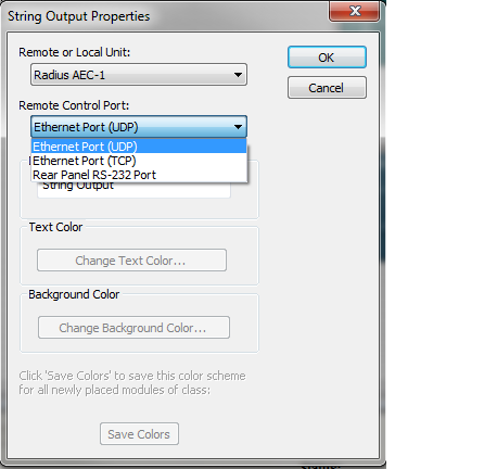
RS-232
This control module sends out a text (ASCII) or binary (hexadecimal) string every time its control input changes from low to high. This module can be used to send RS-232 commands to control a variety of third party devices, e.g. turn on a projector, change a camera position, etc.
The module input accepts a control signal. When the control signal changes from less than 49% to greater than 51%, the string is sent from the units RS-232 port. (The string is only sent from the RS-232 port of the device where the DSP module resides.) Strings may be up to (63) characters or bytes long.
The module has the following controls:
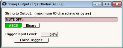
(Where \r is the carriage return)
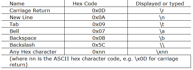
- String to Output (text entry). Enter the string exactly as it should be sent out. Strings are limited to (63) characters or less. The state of the ASCII/Binary buttons control how the string is interpreted and displayed. In ASCII mode, in addition to standard text characters, the following special characters are supported:
In binary mode, data is entered as sequences of bytes in hexadecimal separated by commas. For example, to send out an incrementing sequence of (12) values starting at 7, enter; 7,8,9,A,B,C,D,E,F,10,11,12.
You can toggle between binary and ASCII at any time to edit or view the string.
- ASCII/Binary radio buttons. Selects between either ASCII (plain text) or binary (in hexadecimal) format for interpreting and displaying the string. ASCII mode is the most common and should be used for plain text output. Binary mode allows specifying the exact binary/hexadecimal value of each byte and may be useful in working with those devices that use a binary protocol. See above for further discussion.
- Trigger Input Level display. This shows the current signal level of the control input from 0-100% as a diagnostic.
- Force Trigger button. Pressing this button sends out the string immediately, just as if the input control signal had gone active, or on.
Baud Rate, Deaf Mode and other System Considerations
On Symetrix devices, the RS-232 baud rate is stored in non-volatile memory in each device. It can be set differently for different devices. It is editable from Composer:
1. Right-click on the unit in Design View
2. Select Unit Properties...
3. Select Configure Remote Control Ports...
4. Select the RS-232 Port tab
5. Select the radio button for the desired Baud Rate (1200-230400).
The default baud rate is 57600 bits/second (8 data bits, no parity, 1 stop bit, flow control "none" or "off", aka: 8N1). The baud rate should be set to match what is expected by the connected device.
Note: Please notice that the silk screen on the Edge and Radius RS-232 jack is demonstrating that those ports are RX and TX from the devices perspective. This is where the Edge's RX, or TX can be found, not where the RX, or TX from the 3rd party device
goes.
Depending on how your third party RS-232 device is wired, you may need to use a "null modem" cable, or adapter. Symetrix RS-232 ports DB-0 ports are wired as a "DCE" (Data Communications Equipment) as opposed to a PC which is wired as "DTE" (Data Terminal Equipment). If your third party device is also wired as a DCE, you will need a null modem. A good rule of thumb is that if both devices have the same connector gender (male/female), a null modem is required. If one is female and the other male, then no null modem cable is required.
The string is always output regardless of the state of Quiet Mode (see RS-232 protocol document for more information). A Deaf Mode option is also provided for the RS-232 port This may be useful for devices that respond to commands by sending strings back to Symetrix. It is a good practice to turn on Deaf Mode when using the serial port to control third party devices to avoid issues with their (most likely incompatible) protocol triggering some unexpected command in a Symetrix device.
If you need a string longer than (63) characters, it may be possible to use (2) string output modules to send the longer string out in sequence. The delay logic module may be useful for sequencing the strings. To ensure the strings are sent out in the right order, allow for at least 50ms gap between triggers, i.e. after triggering the first module, wait at least 50ms before triggering the next module.
Since the string only goes out the RS-232 port of the device where the DSP module resides (the string is not send out the RS-485, Ethernet, or any other port.). If the control signal is generated on a different unit, route the control signal to the destination unit and place the string output module there.
For details on controlling specific third party devices, see the appropriate third party devices, see the appropriate third party protocol guide or other documentation. Be sure to set the baud rate correctly, as discussed above. Symetrix is not responsible for the functionality of third party devices and cannot provide support for them beyond making sure that the string you enter is the string the Symetrix device sends out.
UDP/TCP/IP
This control module sends out a text (ASCII) or binary (hexadecimal) string every time its control input changes from low to high.
The following controls are available:
-
String to Output (text entry). Enter the string exactly as it should be sent out. Strings are limited to (63) characters or less. The state of the ASCII/Binary buttons control how the string is interpreted and displayed. In ASCII mode, in addition to standard text characters, the following special characters are supported:
-
ASCII/Binary radio buttons. Selects between either ASCII (plain text) or binary (in hexadecimal) format for interpreting and displaying the string. ASCII mode is the most common and should be used for plain text output. Binary mode allows specifying the exact binary/hexadecimal value of each byte and may be useful in working with those devices that use a binary protocol. See above for further discussion.
-
Trigger Input Level display. This shows the current signal level of the control input from 0-100% as a diagnostic.
-
Force Trigger button. Pressing this button sends out the string immediately, just as if the input control signal had gone active, or high.
Network String Output module
This control module sends out a text (ASCII) or binary (hexadecimal) string every time its control input changes from low to high.
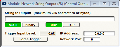
The following controls are available:
-
String to Output (text entry). Enter the string exactly as it should be sent out. Strings are limited to (63) characters or less. The state of the ASCII/Binary buttons control how the string is interpreted and displayed. In ASCII mode, in addition to standard text characters, the following special characters are supported:
-
ASCII/Binary radio buttons. Selects between either ASCII (plain text) or binary (in hexadecimal) format for interpreting and displaying the string. ASCII mode is the most common and should be used for plain text output. Binary mode allows specifying the exact binary/hexadecimal value of each byte and may be useful in working with those devices that use a binary protocol. See above for further discussion.
-
UDP/TCP. Select the communication protocol.
-
Trigger Input Level display. This shows the current signal level of the control input from 0-100% as a diagnostic.
-
IP Address. Put the IP address of the 3rd Party device to which the module will be communicating to.
-
Force Trigger button. Pressing this button sends out the string immediately, just as if the input control signal had gone active, or high.
-
Network Port: Specifies which port to send the string to on the target device.
Note: For 3rd party devices, consult their documentation. To send commands to other Composer-based Symetrix DSPs, use UDP or TCP port number 48631.