4 Channel AEC Input
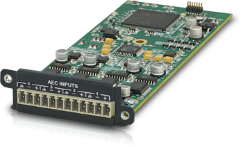
The AEC input card provides four channels of transparent Acoustic Echo Cancellation (AEC), with phantom power, 54 dB of gain and 24 dB of trim. Symetrix' latest generation AEC provides wideband processing with tail lengths up to 250 mS, and convergence times greater than 100 dB/S. Symetrix AEC latency is an industry low 11 mS and near zero bypassed. Each channel of AEC features discrete reference inputs and direct outputs for local reinforcement. AEC processing may be applied to any Symetrix system input while still allowing the card’s inputs to be used. The inputs are electronically balanced using plug-in barrier strip connectors. Control of each input includes gain with metering, trim, mute, AEC, noise cancellation, non-linear processing, and AGC (Automatic Gain Control).
Features:
-
Wideband dedicated processing. Does not consume Edge DSP resources.
-
Zero-latency direct outputs and discrete reference inputs per AEC channel.
-
AEC processing available to the card’s direct inputs or internally routed sources.
-
16 mS AEC latency, up to 250 mS tail length, and greater than 100 dB/S convergence time.
-
Field swappable by certified technicians.
Specifications
Number of Inputs: Four (4) switchable balanced mic or line level with dedicated AEC.
Connectors: 3.81 mm terminal blocks.
Nominal Input Level: +4 dBu with 20 dB of headroom.
Maximum Input Level: +23 dBu.
Mic Pre-amp Gain: 0, 11.8, 24, 44 or 54 dB switchable with ± 24 dB trim.
Mic Pre-amp EIN: < -127dB with 150 ohm source impedance.
CMRR: > 76 dB @ 1 kHz, unity gain.
Input Impedance: 8k ohms balanced, 4k Ohms unbalanced.
Phantom Power (per input): +20 VDC @ 10 mA maximum.
Dynamic Range: > 115 dB, A-weighted.
THD + Noise: < -94 dB, unweighted.
Latency: 0.28 mS (direct), 16 mS (AEC enabled)
Tail Length: 300 mS.
Convergence Time: > 100 dB/S.
Mechanical Data
Shipping Weight: 1 lbs. (0.45 kg)
Certifications or Compliance: EN 55103-1, EN 55103-2, FCC Part 15, RoHS.
A&E Specifications
The device shall provide four analog mic/line inputs with dedicated AEC to an EDGE frame that are adjustable from line to mic level with coarse gain, fine trim and phantom power. Up to four of these devices may be installed in a single EDGE frame for up to sixteen channels of local input. Levels, phantom powers, signal inversions and mutes shall be controllable via software. Audio inputs shall be accessed via rear panel 3.81 mm terminal block connectors.
Audio conversion shall be 24-bit, 48 kHz. The dynamic range shall not be lower than 115 dB, A-weighted with a maximum input level of +23 dBu.
The device shall comply with CE and FCC Part 15 emissions limits. The device shall be RoHS compliant. The mounting plate shall be constructed of cold rolled steel, and mount into a Symetrix EDGE frame I/O card slot. The device shall be aSymetrix Symetrix EDGE 4 Channel AEC Input Card.
Connections
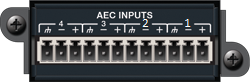 Using standard mic/line cables terminated on one end with terminal block connectors and appropriate connectors for your mic/line sources on the other end, connect the terminal block ends into the AEC Inputs on the card and the opposite ends into your source devices' outputs. Refer to the Audio Wiring Reference for more information.
NOTE: Wiring the inputs to an unbalanced cable will typically result in an input level that is 6 dB lower than the input level achieved using a balanced cable. If wiring to an unbalanced source, you may need to adjust the input level. Refer to Composer Controls in the following section.
'AEC Ins' Module
-
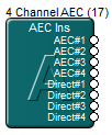
AEC#1,AEC#2, etc. - These are the connections for the local microphone inputs post the AEC algorithm. For the greatest degree of echo cancellation with the highest quality audio conferencing experience, it is recommended that each microphone be connected individually to an input on the 4 Channel AEC Input Card and each microphone should use its own dedicated channel of AEC processing.
-
Direct#n - These are the connections for the local microphone inputs without AEC. The audio is dry, unprocessed, with zero latency added by the AEC algorithm.
The AEC connection provides the acoustic echo cancelled signal.
-
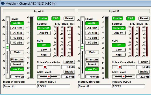
AEC Enable- Engaging this button enables/disables the acoustic echo cancellation algorithm. I most applications this button will be engaged, unless the AEC module is being used for noise cancellation or performing an 'A/B' test of AEC On and Off.
-
CNG- Turn the Comfort Noise Generator On/Off.
-
Level(+4 dBu, -10 dBV, -20 dBu, -40 dBu, -50 dBu radio buttons) - Determines the gain applied by the microphone preamplifier stage. Set this according to the nominal level of the source. The input stage is designed around a nominal input level of +4 dBu balanced with 20 dB of headroom. In other words, a signal of +24 dBu balanced will generate 0 dBFS. The level buttons apply 0, 11.8, 24, 44, and 54 dB of gain respectively so that signals arriving at the inputs at the specified levels will all be the same +4 dBu level following the microphone preamplifier.
-
Reset- Resets the AEC algorithm forcing it to re-converge completely from zeroed out values. Additionally this button resets the AEC meters such as ERL, ERLE, and TER. Toggling 'AEC Enable' freezes the algorithm at the current values or starts the algorithm with the most recent readings. Only "Reset" will fully purge all readings from the AEC algorithm. The reset key on any given channel will reset the convergence on every channel on the card.
-
ERL- Echo Return Loss; The difference in signal level between the audio which is present at the Reference input and the audio measured in the room by the microphones. A negative value indicates a loss and demonstrates a good AEC system performance. Target is 0 to -18dBFS.
-
ERLE- Echo Return Loss Enhancement; The amount the AEC algorithm was able to reduce the echo.
-
TER- Total Echo Reduction; The sum of ERL and ERLE. Echo reduction introduced by the room acoustics (ERL), and the AEC algorithm (ERLE).
-
Source- This selection determines which source will be routed through the AEC processing. Direct will apply AEC processing to the AEC analog input. Selecting Aux will apply the AEC processing to the signal which is routed to the 'AEC Auxes' module.
-
Non-linear Processing- A fancy ducker that works to remove any residual echo that the AEC algorithm missed. Excessive NLP can adversely affect double-talk operation. There are 3 settings; Off, Low and High.
-
Phantom- When depressed, turns on +48 VDC phantom power for the analog input’s mic pre-amp.
-
Invert- Engage this button to change the polarity of the audio signal by 180°, similar to the phase button found on many analog consoles.
-
Low Cut- Engage this button to implement a 4th order, 24dB/Octave High Pass Filter at 100Hz. Frequencies below 100Hz will be attenuated at a rate of 24dB/Octave. Frequencies above 100Hz will pass unaffected.
-
Noise Cancellation- The level of attenuation implemented on constant room noise.
-
AGC Level- Automatic Gain Control: Takes signals of indeterminate levels up to a target RMS output level while maintaining program dynamics.
'AEC Refs' Module

- Ref#n - This is the connection for the reference signal, the audio that needs to be removed from the microphone input and prevented from being passed along to the far end. Whatever audio is connected to this input is the audio the AEC algorithm will cancel out. This may be audio from a telephone hybrid, or other tie-line to the remote location and is often the same signal that is sent to the loudspeakers. If the intention is to use the 4 Channel AEC Input Card’s analog input or aux input for noise reduction only, leave this input unconnected.
'AEC Auxes' Module

- Aux#n- These inputs are used for routing any audio through the AEC algorithm to remove acoustical echo without having a source connected to the physical inputs of the 4 Channel AEC Input Card’s analog input. The signal placed into these inputs can be a statically mixed bus of multiple microphones, a single mic routed into the DSP over Dante, or a source in which noise cancellation is desired.
For more information on AEC, please see the Acoustic Echo Canceller section.