Symetrix 4 Channel Digital Output
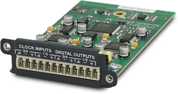 A single Edge frame has four configurable card slots, providing up to 16 channels of local I/O. The 4 Channel Digital Output card provides four channels of digital output in AES or S/PDIF format with clock inputs to sync the outputs to a sample rate of your preference. The outputs are provided on plug-in barrier strip connectors. Control of each output includes gain with metering and mute.
Features:
-
Digital audio output card. Up to 4 cards per frame.
-
Supports AES/EBU or S/PDIF.
-
Nominal output sample rate of 48 kHz.
-
Supports external clock input of 12 to 96 kHz.
-
Field swappable by certified technicians.
Specifications
Number of Outputs: Two (2) pairs of switchable AES or S/PDIF format (4 channels total).
Connectors: 3.81 mm terminal blocks.
Nominal Output Level: -20 dBFS (+4 dBu with 20 dB of headroom).
Maximum Output Level: 0 dBFS (+24 dBu).
Output Impedance: 110 Ohms (AES), 75 Ohms (S/PDIF).
Dynamic Range: > 128 dB, unweighted.
THD + Noise: < -125 dB, unweighted.
Nominal Sample Rate: 48 kHz.
Sample Sync Range: 12 to 96 kHz.
Latency: 2.1 mS @ 48 kHz.
Mechanical Data
Shipping Weight: 1 lbs. (0.45 kg)
Certifications or Compliance: EN 55103-1, EN 55103-2, FCC Part 15, RoHS.
A&E Specifications
The device shall provide two pairs of digital outputs (4 channels total) to an EDGE frame that are adjustable with fine trim and selectable in format between AES or S/PDIF. Up to four of these devices may be installed in a single EDGE frame for up to sixteen channels of local output. Levels, mutes, clock sources and formats shall be controllable via software. Audio outputs shall be accessed via rear panel 3.81 mm terminal block connectors.
Audio format shall be 24-bit, 48 kHz with option to output 12 to 96 kHz using an external clock source. The dynamic range shall not be lower than 128 dB,unweighted with a maximum output level of 0 dBFS (+24 dBu).
The device shall comply with CE and FCC Part 15 emissions limits. The device shall be RoHS compliant. The mounting plate shall be constructed of cold rolled steel, and mount into a Symetrix EDGE frame I/O card slot. The device shall be aSymetrix Symetrix EDGE 4 Channel Digital Output Card.
Connections
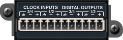 The 4 Channel Digital Output Card consists of 2 digital outputs; each capable of passing a 2 channel digital stream per input. Each output can be configured for either unbalanced S/PDIF (a single 2 channel stream over the + and ground) or balanced AES/EBU (a single 2 channel stream over +, - and ground).
Using 100-Ohm (balanced, AES) or 75-Ohm (unbalanced, S/PDIF) cables terminated on one end with terminal block connectors and appropriate connectors for your destination devices on the other end, connect the terminal block ends into the Digital Outputs on the card and the opposite ends into your destination devices’ inputs. These outputs use a sample rate of 48 kHz by default. If you need a different sample rate, connect an appropriate Word Clock, AES-3/11 clock or S/PDIF clock source to the corresponding Clock Input(s) on the card. Then select External as the clock source in the controls shown below.
Composer Controls
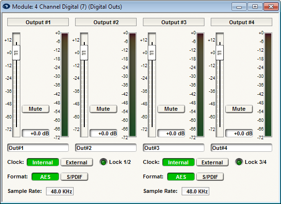
Channel Name (static label): Displays the input channel number.
Gain (fader): Adjusts the gain of the signal in the digital domain. It provides fine gain control between +12 dB to Off in 0.1 dB steps and can be used to optimize signal levels and headroom. Set this according to the signal level expected by the downstream device.
Mute (button): When depressed, this channel will be muted. The muting happens in the digital domain.
Channel Label (user-editable field): Double-clicking in this field allows direct text entry of a user-specified label for the channel.
Meter (bar graph): Shows the level output from the Digital Outs module (post Gain and Mute).
Clock (Internal, External radio buttons): Sets the clock source for each output pair. Internal results in a digital output with a clock rate of 48 kHz. If you need a different sample rate for your receiving device, you may connect a clock source of the appropriate sample rate to the clock input(s) and the digital outputs will output at that rate. Valid clock sources are Word Clock, AES-3/11 or S/PDIF ranging from 30 to 200 kHz.
Format (AES, S/PDIF radio buttons): Determines the digital output format for each output pair.
Sample Rate (display): Indicates the current output sample rate for each output pair.