I/O Card Removal and Replacement
ESD Warning
This product can be damaged by electrostatic discharge (ESD). When handling, care must be taken so that the devices are not damaged. Damage due to inappropriate handling is not covered by the warranty.
The following precautions must be taken:
- Do not open the protective conductive packaging until you have read the following, and are at an approved anti- static work station.
- Use a conductive wrist strap attached to a good earth ground.
- Always discharge yourself by touching a grounded bare metal surface or approved anti-static mat before picking up an ESD-sensitive electronic component.
- Use an approved anti-static mat to cover your work surface.
- Always remove power from the unit before removing the lid.
- Always replace the lid before re-powering the unit.
- Ensure a blank panel is installed into any slot not containing an I/O card.
Card Set-up and Configuration
Once you are properly grounded, follow this sequence of steps to properly set-up and configure Symetrix I/O cards in your unit.
Removal: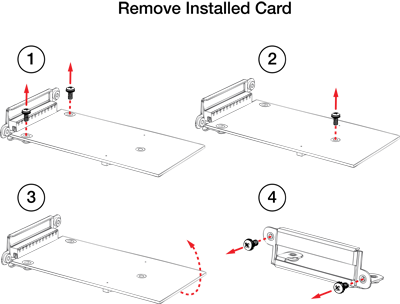
- First, you must remove the lid. To do this, 3 Phillips head screws need to be removed from the top of the frame. Slide the lid back and then up when removing. There is a lip that holds the front down to the chassis.
- If your unit has blank filler panels in the card slots, unscrew and remove them by removing the two black screws located on the outside of the frame.
- To remove an installed card, first remove the 2 stainless steel screws that mount the card bracket to the card. These screws are located on the inside.
- Next remove the stainless steel Phillips head screw from the top of the card. Gently pull the card up to disconnect the 50-pin connector. The card is no longer attached to the frame. Carefully remove the card from the chassis.
- Remove the bracket for the I/O card by removing the two black screws located on the outside of the frame.
Replacement: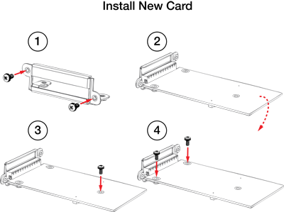
- To install a new card, mount the bracket for the new I/O card to the frame chassis using the two black screws provided.
- Next, align and feed the connectors on the I/O card through the opening in the bracket and align the single screw hole in the card with the standoff on the motherboard. Visually look through this hole and align with the standoff and then, carefully, apply an even downward pressure until you feel the card seat into the 50-pin socket. You will likely need to carefully move the board side to side to align the 50-pin connector. Use one of the stainless steel screws provided and mount the board to the standoff. Do not over tighten this screw. The 50-pin connector on the Symetrix cards should not be under any tension when properly installed.
- Now, install and tighten the 2 remaining stainless steel screws that mount the bracket to the card. This should ALWAYS be the last step before replacing the lid.
- Finally, replace the lid.
The IN, OUT, AEC and DIGI LEDs on the front of the unit will illuminate in combination to indicate the card type installed. For example, an IN illuminates to indicate an analog mic/line input card, whereas IN and DIGI illuminate to indicate a digital input card. If the card is installed properly the card type LED will illuminate.