Shure
MXWAPT2, MXWAPT4, or MXWAPT8
Note: Before the Shure Microflex Wireless system can be fully integrated with a Composer Site File, there are a few things that must be setup using the web-based administration interface on the MXWAPT2, MXWAPT4, or MXWAPT8. Click here for the pre-Composer Setup instructions.
A Shure MXWAPT2, MXWAPT4, and MXWAPT8 can be added to the site view.
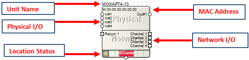
All of the following features are managed in the Unit Properties dialog. To access the Unit Properties, right-click on the unit module in the Site View and choose “Unit Properties...”
-
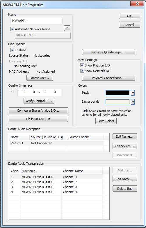
Name- It is recommended to assign a unique unit name for each unit in the design based on the unit's purpose or location. Composer will always append a unique numeric identifier to this name.
-
Network Name- When Automatic Network Name is checked, the network name is auto-generated from the unit name. Network names cannot contain special characters or spaces and must be unique.
-
Enabled- When the enabled box is checked, the unit must be physically present on the network for a Push of the site file to the hardware. When the enabled box is unchecked, a X will appear on the unit module in the Site View, and the unit will not be required to be physically present for the Push of the site file.
-
Locate Unit...- Opens the 'Locate Hardware' dialog box to select the unit to connect to.
-
Control Interface IP- This is the control IP address for the located Shure MXWAPT device.
-
Verify Control IP...- Verifies that the control IP address in the above field is correct.
-
Configure Shure Analog I/O...- Opens the Configure Shure MXWAPT dialog box to set the gain of the inputs.
-
Flash MXWAPT's LEDs -Sends the flash command to the unit to confirm communication. All LEDs on the front of the unit will flash.
-
Network I/O Manager... -Opens the Network I/O Manager dialog. Click here for instructions on how to program Network Transmit and Receive Buses.
-
View Settings- When either Show Physical I/O or Show Network I/O check box is checked, the unit module in the Site View will show the corresponding connections.
-
Physical Connections...- Opens the Edit Physical Connections dialog.
- Colors -The text color and background color for the unit module can be customized. To save custom color settings made here as defaults for future units, click the Save Colors button.
Pre-Composer Setup Instructions
Before the Shure Microflex Wireless system can be fully integrated with a Composer Site File, there are a few things that must setup using the web-based administration interface on the MXWAPT2, MXWAPT4, or MXWAPT8.
The easiest way to do this is to put the PC, MXWAPT, and Charging Station (with mics inserted) on a common isolated switch (no LAN or Internet connection). Note that the MXWAPT requires Class 0 PoE. Shure recommends the Cisco-SG200-08P switch. A suitable PoE injector should also suffice.
Once all devices are connected and powered up, they should default to link-local addressing within a reasonable amount of time, typically 30 seconds to a minute. Shure has a discovery application available for Mac and Windows on their web site available for download. Copy and paste this link into your browser:
http://www.shure.com/americas/products/software/utilities/shure-web-device-discovery-application
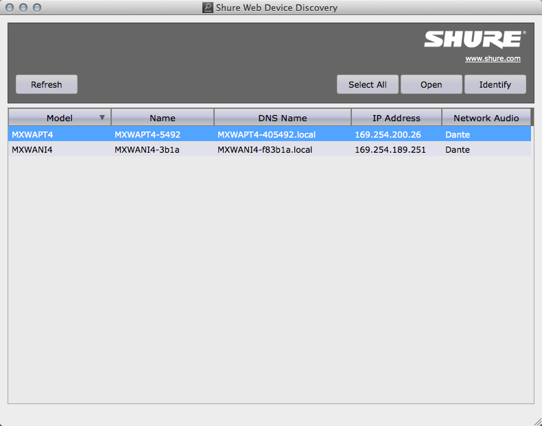
Using this application, launch the applicable MXWAPT’s web administration interface. Within this interface,the following actions must be performed before use with Composer:
-
Set the MXWAPT’s Control Interface to static IP.
-
-
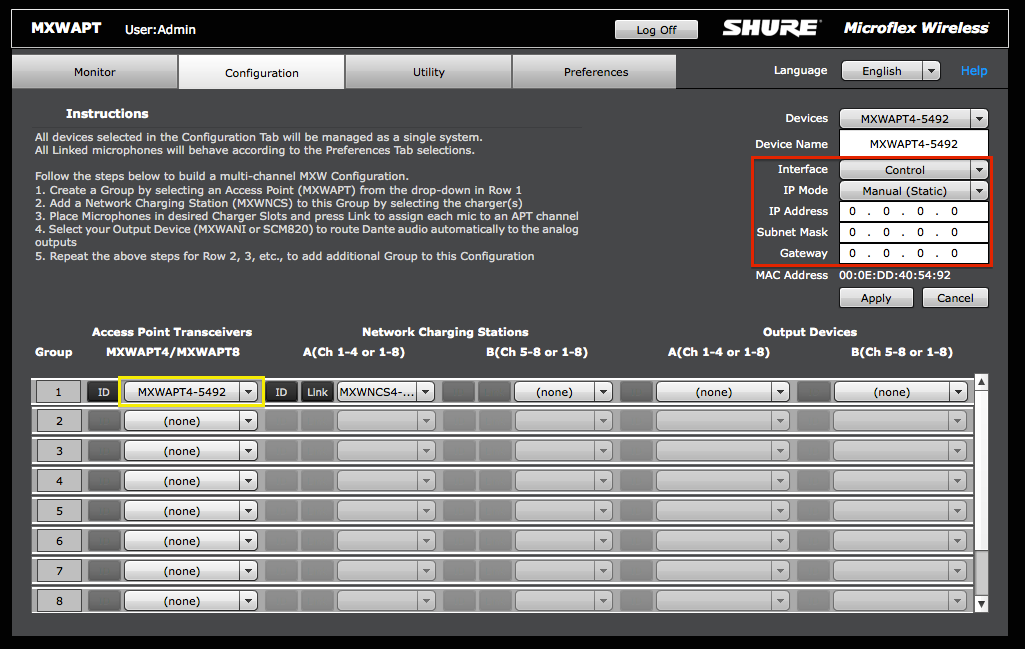
Click on the Configuration tab.
-
For Group 1, select an Access Point Transceiver from the drop down menu circled in yellow. If you are unsure which APT you are dealing with, use the ID button to locate it.
-
Now, in the upper right area circled in red, make sure the “Control” Interface is elected then select “Manual (Static)” from the IP Mode drop-down.
-
Fill in the IP Address, Subnet Mask and Gateway fields with the appropriate IP information and click “Apply”.'
-
-
- Repeat for any additional Groups.
-
Link a Charging Station to an MXWAPT.
-
-
Click on the Configuration tab.
-
For Group 1, select an Access Point Transceiver from the drop down menu circled in yellow. If you are unsure which APT you are dealing with, use the ID button to locate it.
-
For Group 1, select a Charging Station from the drop down menu circled in red. If you are unsure which Charging Station you are dealing with, use the ID button to locate it.
-
For Group 1, click the Link button which the blue arrow is pointing to.
-
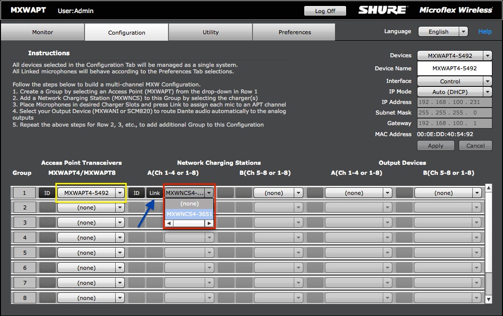
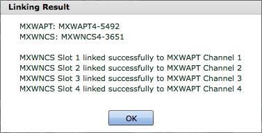
You should be presented with a similar message shown below:
-
- Repeat for any additional Groups.
-
Configure the transmitter buttons and LEDs for remote use.
-
-
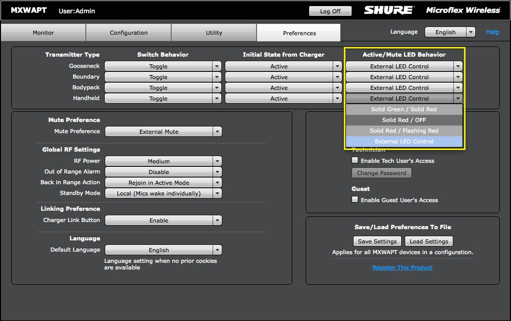
Click on the Preferences tab.
-
For each transmitter type intended for use with Composer, set its Active/Mute LED Behavior to “External LED Control” as circled in yellow.
-
-
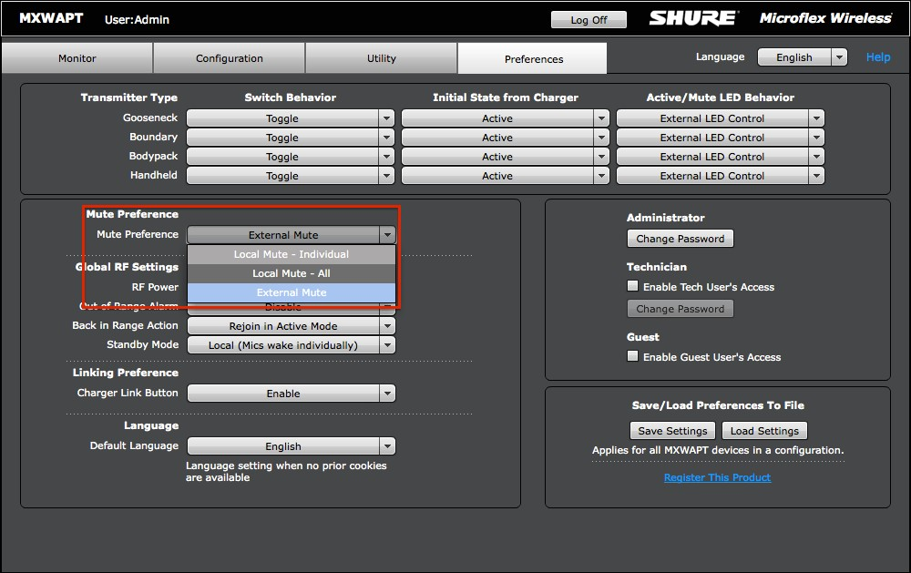
- Now set the Mute Preference to “External Mute” as circled in red. This is especially important for mics used in AEC systems as you will get the best performance muting in DSP post-AEC as opposed to muting at the mic.
After you have completed these steps, you may place the Shure APT and Charging Station on the AV or Corporate LAN, or add the Symetrix units to the Shure LAN to continue system configuration.
MXA310 & MXA910
Note: Controlling the Shure MXA310's Light Ring requires it to be properly configured. Click here for the setup instructions.
A Shure MXA310 or MXA910 can be added to the site view.
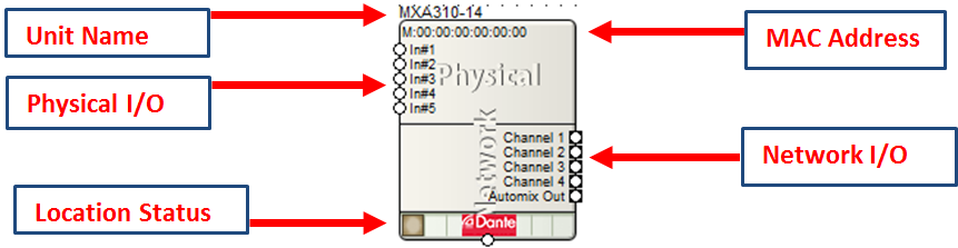
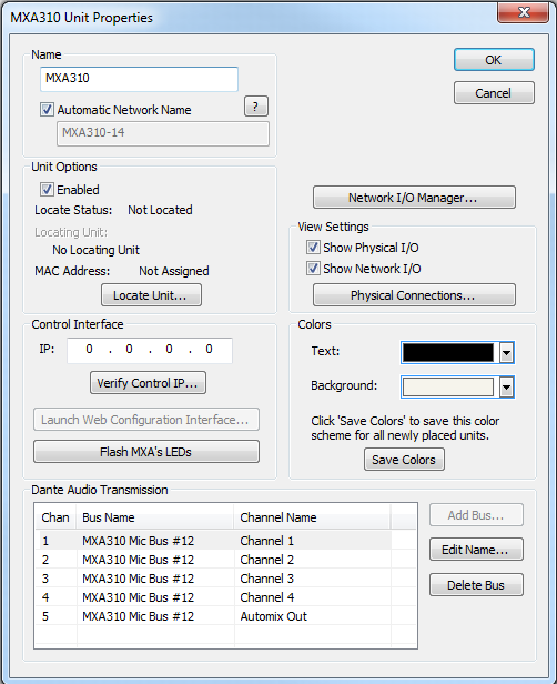
All of the following features are managed in the Unit Properties dialog. To access the Unit Properties, right-click on the unit module in the Site View and choose “Unit Properties...”
-
Name- It is recommended to assign a unique unit name for each unit in the design based on the unit's purpose or location. Composer will always append a unique numeric identifier to this name.
-
Network Name- When Automatic Network Name is checked, the network name is auto-generated from the unit name. Network names cannot contain special characters or spaces and must be unique.
-
Enabled- When the enabled box is checked, the unit must be physically present on the network for a Push of the site file to the hardware. When the enabled box is unchecked, a X will appear on the unit module in the Site View, and the unit will not be required to be physically present for the Push of the site file.
-
Locate Unit...- Opens the 'Locate Hardware' dialog box to select the unit to connect to.
-
Control Interface IP- This is the control IP address for the located Shure MXA310/910 device.
-
Verify Control IP...- Verifies that the control IP address in the above field is correct.
-
Launch Web Configuration Interface...- Launches the default web browser to the indicated control IP address, directing to the Shure web interface to configure the selected MXA device.
-
Flash MXA's LEDs -Sends the flash command to the unit to confirm communication. All LEDs on the front of the unit will flash.
-
Network I/O Manager... -Opens the Network I/O Manager dialog. Click here for instructions on how to program Network Transmit and Receive Buses.
-
View Settings- When either Show Physical I/O or Show Network I/O check box is checked, the unit module in the Site View will show the corresponding connections.
-
Physical Connections...- Opens the Edit Physical Connections dialog.
-
Colors -The text color and background color for the unit module can be customized. To save custom color settings made here as defaults for future units, click the Save Colors button.
Setting the MXA310 Light Ring/Segments to be controlled via Composer
In order to control the light ring/segments of the Shure MXA310 microphone via Remote Logic Output modules within Composer, there are a few settings that need to be set in the Shure web GUI for the device.
After the unit has been located within Composer and the Control IP has been entered and verified, click the Launch Web Configuration Interface... button in the MXA310's unit properties dialog.
Note: The PC used for the web configuration needs to be on the Dante network along with the MXA310.
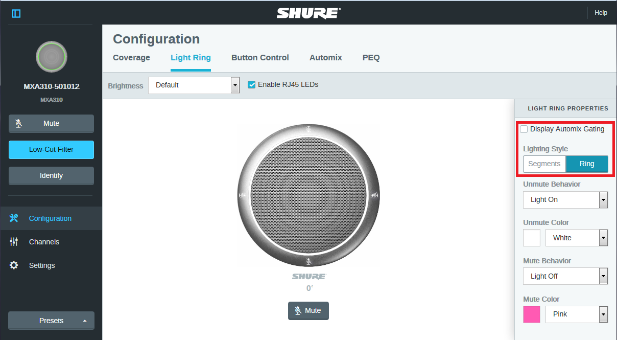
1. Under the Configuration menu, Click on the 'Light Ring' text and make sure that 'Display Automix Gating' is unchecked (this checkbox only appears when the MXA310 'Mute Control Function' is set to Local or Disabled). Also select the 'Lighting Style' to control the entire Ring or the individual Segments as desired.
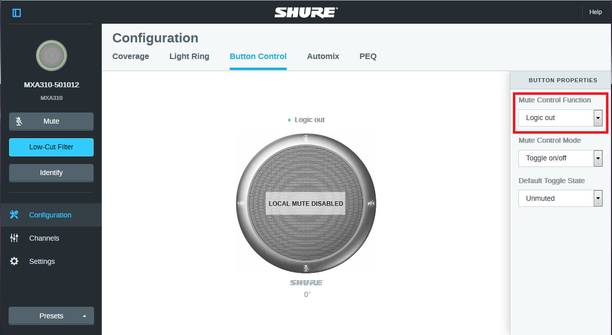
2. Next click the 'Button Control' text and select 'Logic out' for the 'Mute Control Function'.
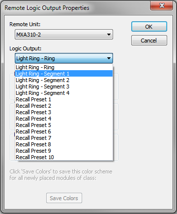
3. Within Composer, place a Remote Logic Output module and select the appropriate Light Ring option that matches the Lighting Style chosen for the MXA310.
The Light Ring can now be controlled via Composer and control logic to use it any way you want.
Note: It may be necessary to power cycle the MXA310 for communication to be established for remote logic control.