Gating Automixer
Channel Controls and Indicators
Master Controls and Indicators
Composer's Gain Sharing Automixers feature fast, smooth-sounding operation and require little adjustment and set up time. However, for some users, a gating algorithm that limits the total Number of Open Microphones (NOM) is preferable. Composer's gating automixer modules are built around an adaptive threshold algorithm that is easy to set up and doesn't require setting a fixed threshold. (For a further discussion of the differences between gating and gain-sharing automixers, see Automixer Technology.
There are three classes of gating automixers. Those simply calledGating Automixersare for stand-alone operation, i.e. a single module with up to (16) channels. TheMaster Gating AutomixersandSlave Gating Automixersare for applications where larger modules are required. A single master and one or more slaves can be linked to achieve a composite automixer with up to (512) channels. All controls on the master unit apply to all connected slaves. In each of the three classes, the following channel counts are available; 4, 6, 8, 12, and 16.
The Symetrix gating automixer uses an adaptive noise threshold for every channel. A channel's signal must exceed the threshold by a programmable amount to come on. Hence, channels do not come on in the presence of fixed noise, e.g. equipment fans or HVAC. Furthermore, additional module features prevent multiple microphones from gating on when a single person is speaking. As more channels gate on, the over-all level is reduced to prevent feedback. This is referred to as NOM Attenuation and is also programmable. The total NOM may also be limited. When this limit is reached, a multi-level priority scheme determines which microphones are allowed to gate on.
Module Inputs and Outputs. Automixers have inputs for each channel. Each channel also has a direct out that is affected by the automatic gain (including NOM attenuation) channel fader, and channel mute (i.e. it is post auto-gain, post fader and post mute).
There is also a mix output that is the sum of all the direct outputs scaled by the master gain. The Master and Slave modules have additional inputs and outputs for linked operation which will be discussed below.
Channel Controls and Indicators
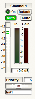 Auto button. Each channel has an Auto on/off button. Turn this on for all channels that require automixing. Turn this off, for example if you have a channel of background music or presentation audio that you want a fixed level, or un-auto-mixed signal processing. The Auto function could also be turned off in the event that there was a "Chairperson" microphone that you wanted to remain always on. When a channel's Auto button is off, its gain will not be adjusted automatically, i.e. its gate and NOM attenuation are bypassed. In addition, the signal level on this channel will not affect other channels (i.e. it will not affect the automix gain calculations) and it will not be included in the NOM count.
Channel Fader. The channel fader controls the mix level and direct output level for the channel. The fader is post auto-gain. That is, nothing you do with this affects the automixing operation. You can also control the channel level precisely by clicking in the text box and entering a dB value.
Mute Button. The Mute button mutes the channel. Muted channels never come on and aren't included in the NOM count. However, a muted channel that has Auto on may still have some effect on the automixer algorithm. This enables the creation of a "Dead zone" as described below. To mute a signal and prevent it from affecting the automixing operation, turn Mute on and the Auto off. The Mute for each channel mutes the channel in the mix and also mutes the direct out.
Priority Control. The priority control affects the automix algorithm by allowing higher-priority channels to take precedence over lower ones. This control can take any whole number value between 0 (lowest priority) and 10 (highest priority) with 5 as the default. You may adjust the priority either using the slider control, or by clicking in the edit box and entering a whole number between 0 and 10. Increasing the value increases the priority.
The priority setting comes into play only if the NOM Limit is met or exceeded. In that case, higher priority channels can turn off lower priority channels, or prevent them from coming on. If priorities are equal, the first-on channel wins. If all channels are of equal priority, leave all priorities set to 5.
Default button. The Default button selects a channel to come on when all channels are off. In other words, if no one is speaking, the default microphone will come on. Only one channel can be selected as the default. Turning on Last On in the master section turns off all Default buttons. (Default channel and Last On channel are mutually exclusive settings.)
Channel name. A space is provided at the bottom of each channel strip to name the channel. If desired, click in the text box and enter a name.
On LED. The On LED turns on to indicate when a channel is on. It is activated when audio activity turns the gate on, or if Auto is off. For muted channels, this LED never comes on. this LED may be assigned a Control Number. Doing so allows external devices to monitor the state of each channel via Polling, or pushed data, e.g. to control camera switching.
Meters. Each channel has two meters. The tricolor In meter indicates that level of the input signal. This meter is pre-fader and pre-auto-gain. It shows the average signal level of components primarily in the voice band. The red Gain meter shows the auto-gain of that channel, i.e. the gain due to the gate and NOM attenuation. It does not include the settings of the channel fader. If the channel is not in Auto mode and unmuted, this meter will indicate 0dB.
Master Controls and Indicators
These controls are only available on stand-alone and master modules. Slave modules follow the master's settings.
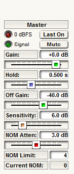 Gain and Mute. The master section includes master gain and mute settings. These affect only the mix output, not the channel direct outputs.
Metering LEDs. The Signal (signal present) and 0dBFS LEDs indicate the level of the mix output.
Last On. Depressing the Last On button ensures the last microphone remains on even if no speech is detected. This guarantees that at least one microphone will always remain on to prevent dead air. (Alternatively, a specific channel may be designated to come on in this scenario, as selected by the Default button on each channel).
Hold. The Hold slider adjusts the length of the time a channel remains on after the speaker stops speaking. Use a time long enough so that short pauses between words and sentences don't cause a channel to turn off. If excessive chattering (turning on and off) is occurring, a longer hold often helps. However, too long a hold time can prevent the next talker from gating on when the NOM count is reached.
Off Gain. The Off Gain sets the level of all channels that are gated off. A higher setting (e.g. -20dB) may be useful to ensure there is some room tone when all microphones are off, in cases where Last On, or a Default channel is not used. Channels that are muted are fully attenuated regardless of this setting.
Sensitivity. The Sensitivity slider controls how far above its adaptive noise threshold a channel must be to gate on. If channels gate on too easily for quiet noises, increase this setting. In our experience, noisy rooms (e.g. a lot of fans) require a lower setting than quiet rooms. This is because in quiet rooms, even low-level sounds are significantly louder than the noise floor.
NOM Attenuation. The NOM Attenuation slider affects the amount by which all channels are attenuated as more microphones come on. The parameter represents the attenuation when exactly two microphones are gated on and the additional attenuation per every doubling of open microphones.
For example, with the default setting of 3dB, there is no NOM attenuation for (1) microphone on. For (2) microphones on, the output is attenuated by 3dB. For (4) microphones, there is 6dB of gain reduction and for (8) microphones there would be 9dB of attenuation, etc. The default 3dB setting results in a mathematically ideal constant RMS output level for unrelated signals, (For perfectly correlated signals, 6dB is the ideal). Settings above 3dB often result in the total output level decreasing slightly as more microphones gate on. On the other hand, higher settings are safer in terms of preventing feedback, though typically the 3dB setting works well.
NOM Limit. The NOM Limit sets the maximum number of open microphones. Channels not in Auto, or channels that are muted are not counted toward this limit. For stand-alone automixers, the limit can be as large as the number of channels in the module. For master automixers, 512 is the maximum. The minimum acceptable limit is 1 in both cases.
Dead Zones
The Gating Automix algorithm allows the integrator to create dead zones. The premise behind the creation of a dead zone is the sounds originating from that area will never trigger the automixer. A dedicated microphone is required to create a dead zone. Sound originating from near this microphone will not cause the automixer to gate on, even if it is also picked up by other microphones. For example, consider the case of a piece of equipment that has a noisy fan that turns on and off periodically. Without a dead zone, the microphone closest to the equipment will most likely turn on briefly every time the fan comes on. This can be prevented by placing a microphone near the equipment and setting it up for dead zone operation.
To designate a microphone as a dead zone, mute that channel but leave 'Auto' on. Since the channel is muted, that microphone will never gate on, but because 'Auto' is on, it will be taken into account by the algorithm and prevent other microphones from gating on, even those that also "hear" signals originating near the dead zone microphone.
NOTE: In order to truly kill an audio input signal into the Gating Automixer, it is advisable to mute the input at a gain stage before it reaches the Automixer. This should be done, or a preset should be cued when the mute is cued in order to disengage "Auto" for that channel. Only by disengaging "Auto", or by muting the audio input at a gain stage before it enters the Automixer will you be able to avoid the Dead Zone affect on muted channels, if it is undesirable.
Linked Operation
Individual automixers can be linked together to form larger automixers modularly. Linking is accomplished by daisy chaining a few signals between modules. Note that room combining is not supported with gating automixers. Do not attempt to use the gating automixers with the Room Combining modules! Gain sharing automixer's slave output "Chain" is that which carries the mixed gain sharing information onto other mixers. The "Link" output of Gating Automixers will have NOM and gate information which is not transferrable through combine modules to the master.
Linked by Daisy Chaining
To link multiple automixers, you must designate one as a master and the other(s) as slaves. Use a Master Automixer for the master and Slave Automixer modules for the slaves.
Connect the Link output in a daisy chain (complete loop) starting with the master. Wire the Link output of each module to the Link In input of the next device. Be sure to complete the loop by wiring from the last slave to the first master. If you are using the mix outputs, also connect the Mix output to the Mix In input in a daisy chain, starting with the master and ending with the last slave. The complete mix out will be available from the Mix output of the last slave. (The mix daisy chain is only required if you are using the mixed output. It is not required for general linked automixer operation.) Optionally, finish the loop by connecting the last slave back to the master. This allows the master to properly meter the mix signal, but isn't required for any other reason.
The figure to the left shows the correct connections for the (3) linked automixers. The wires are color-coded to make following them easier. The gray/blue connection from the last slave Mix back to the master is only required for proper metering on the master.
The Link connection must be implemented with a fully digital signal path, i.e. control through Dante, or a single wire within the same unit.Do not attempt to use an analog tie line for this connection. Do not pass this signal through any other module such as a gain, selector, etc.The link signal encodes binary information into an audio signal and passing it through other modules, or converting to analog will destroy some of this information. (Technically, the Mix signal could use an analog signal path without significant degradation, but a digital path is strongly recommended.)
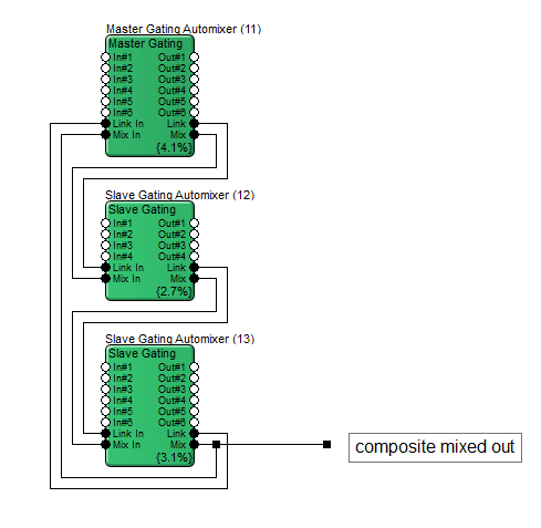
NOTE: The Link signals are not intended to be listened to. Do not route these signals to your loudspeaker system!
Linked automixers act as one large automixer in terms on NOM count, Priority, etc. All parameter adjustments made on the master affect the slaves.
One potentially tricky issue is the Default/Last On setting, so that deserves further discussion. It is possible to designate more than one channel as the 'Default' in a linked automixer. In this case, the master resolves the discrepancy as follows:
-
If the master has Last On, or any channel Default button selected, that setting is used for the entire linked automixer.
-
If not, then if the first slave as any Default button selected, that is used.
-
If not, the process continues with each slave in order of their daisy chain connection, with the first Default value used.
-
If no modules have Default buttons selected, the Default/Last-on feature is disabled (i.e. all microphones may gate off).
Slave modules may reside in different units from the master and from each other. Use Dante to route the Link and Mix signals between modules if they are on different units.
Delay in the loop may negatively impact performance. For this reason, try to minimize the round-trip delay of the link signal. The Dante bus works well for this due to the fact that it has very low system wide latency. If there is an option between using a greater number of small automixer modules, or fewer large modules, choose the latter option. The fewer modules there are, the lower the round-trip delay will tend to be.
In some cases, audio channels can be routed to another unit and a single module can be used.
Limitations
Linked automixers are limited to (512) total channels. Any additional channels will simply be stuck permanently off. In addition, there is a limit of (64) total modules in a chain, i.e. one master and up to (63) slaves. Again, additional modules will be stuck permanently off.
Note: If (8) channel modules are used, (64) modules can be used to create the maximum (512) channel automixer.
Linking using Automix Combiners
Room combining isnotsupported with gating automixers. Do not attempt to use the gating automixers with the Room Combining modules!