xIO XLR - Software
Properties Window
The properties window allows controlling the properties for the xIO XLR expanders as with other xIO devices. However, like the xIO Bluetooth RCA-3.5mm device, there is no option to disable use of Intelligent Modules for device control. Dialog-based control is not supported for new xIO devices going forward.
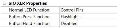
All xIO XLR devices have three device specific properties available in the properties window.
-
Normal LED Function– Specifies the normal function of the LEDs.
-
- Control Pin - The Intelligent Module control pin inputs are used to set the LED colors and brightness. The incoming value is sampled every 0.5 and applied to the LEDs. The incoming values is shown in the Intelligent Module UI as well.
-
Off - The LEDs are off
-
Phantom Power - The LEDs show Phantom Power operation for the corresponding XLR
-
- Amber - Phantom Power is on
- Off - Phantom Power is off
-
Signal Level - The LEDs show Signal/Clip information for the corresponding XLR
-
- Red - The signal is clipping
- Green - The signal is present
- Off - No signal is present
-
Button Press Function - Controls what happens when pressing and releasing the button on the unit. Two gang devices have two buttons but both are programmed to react the same
-
- Flashlight - The LEDs will temporarily light white to light a dark area until the button is pressed again or after 10 seconds elapses, when they will return to configured normal operation.
- Phantom/Level Toggle - The LEDs will first temporarily show the Phantom Power status as described above. After a second press, the LEDs will them temporarily show the Signal Level as described above. After a third press or after 10 seconds elapses, when they will return to configured normal operation.
- Control Pins - The LEDs will temporarily light with the values from the Control Pins as described above until the button is pressed again or after 10 seconds elapses, when they will return to configured normal operation.
-
Disabled - The front panel button does nothing when pressed.
-
Button Hold Function - Controls what happens when pressing AND holding the button on the unit for some amount of time and then releasing. Two gang devices have two buttons but both are programmed to react the same.
-
- Disabled - Pressing and holding has no function.
-
Reset - depending on the amount of time the button is held before releasing, one of the following functions will occur with a unique LED pattern shown for each option.
-
- 3 seconds - the unit will reboot. This is indicated by a purple flashing sequence occurring once after 3 seconds.
- 10 seconds - the unit will reset the IP settings and reboot. This is indicated by a purple flashing sequence beginning again after 10 seconds and then continuing until 20 seconds is reached.
- 20 seconds - the unit will reset to factory defaults and reboot. This is indicated by the LEDs stopping flashing and turning solid purple when 20 seconds is reached..
Unit Properties Dialog
The Unit Properties dialog is similar as for other xIO devices. The Dante routing options are modified depending on the number Dante channels available in each direction. Note the option to disable use of Intelligent Modules is removed.
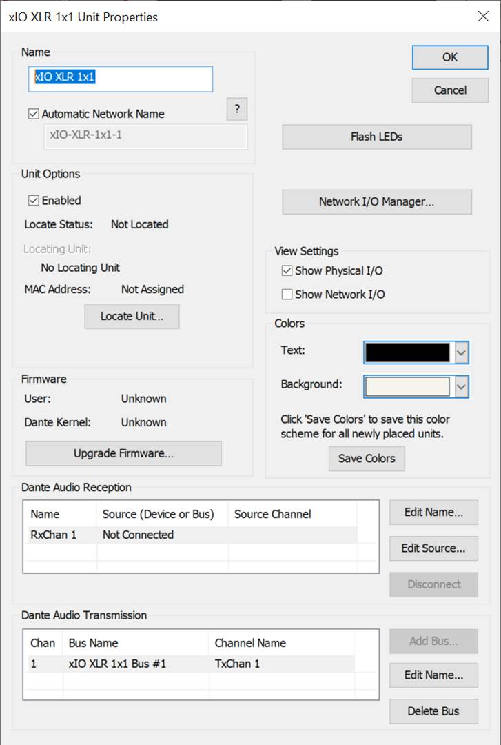
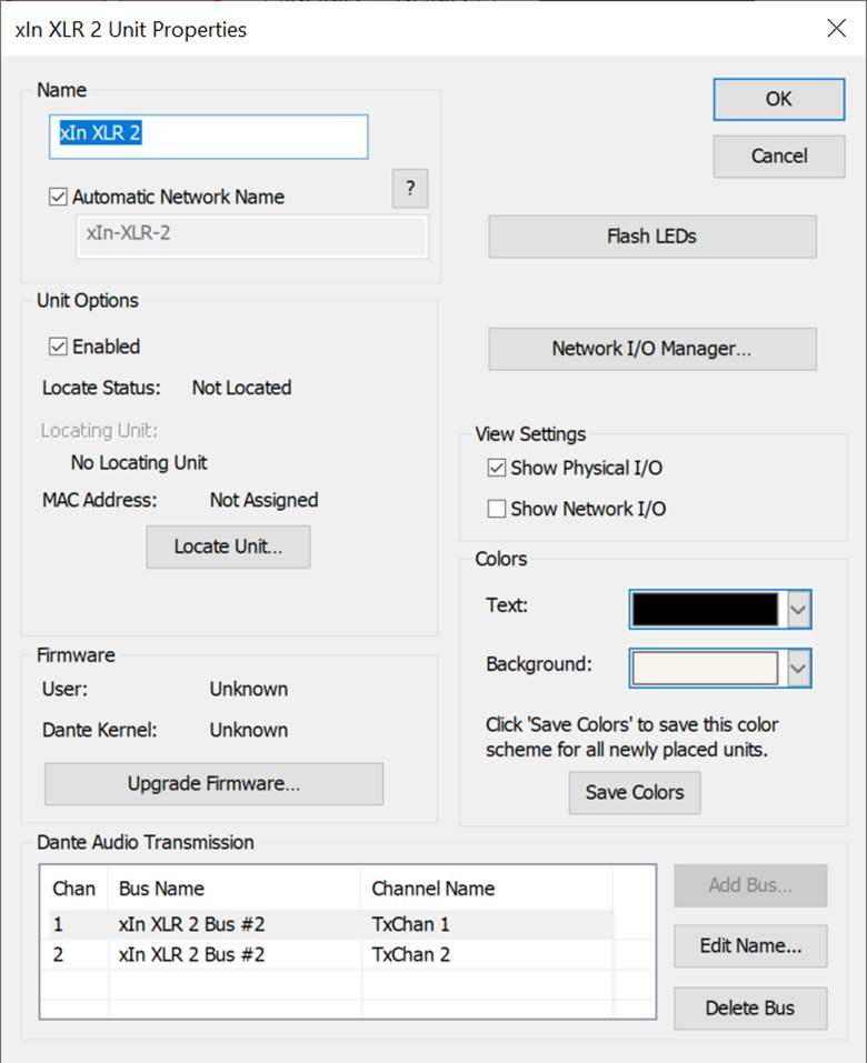
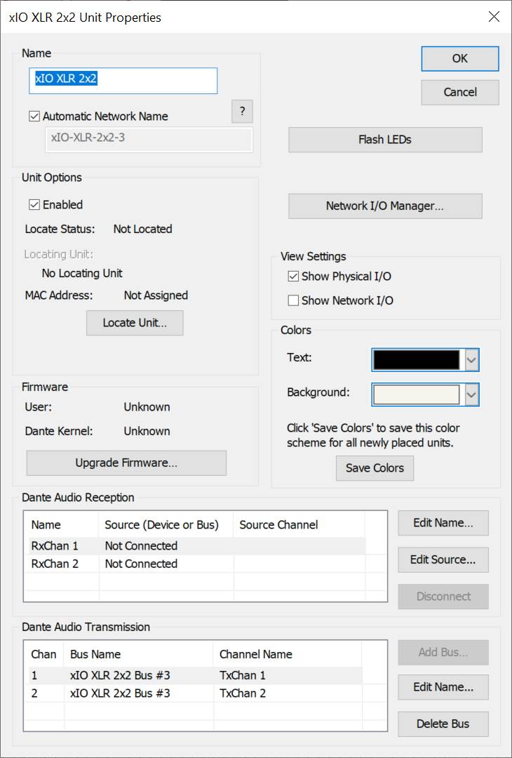
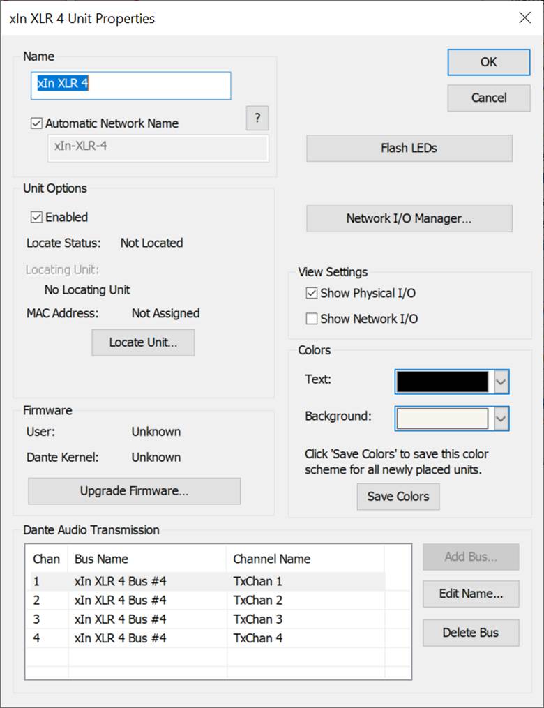
The Unit Properties dialog will show the current “User” and “Kernel” firmware versions if located and known. The “Upgrade Firmware…” button allows changing the firmware of a located device.
The Upgrade firmware dialog is presented and either user or kernel firmware can be updated. By default, it detects if an upgrade is necessary and displays the proper versions.
Each flavor of xIO XLR device has a different kernel firmware file, but they all share a new user firmware file.
The kernel file extensions are “.xioxlr1x1:, “.xinxlr2”, “.xioxlr2x2”, and “.xinxlr4”. The user file extension is “.xioxlr”.
These extensions may change as real product names are applied.
Design View
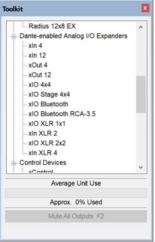
As with any xIO device, once placed in a site, a DSP design view presents those devices in the toolkit for placement of a control module.
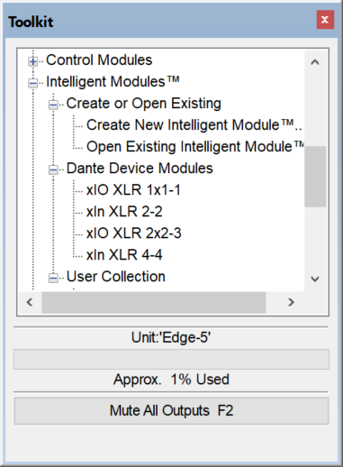
Intelligent Modules can be placed from the toolkit to the design. An Intelligent Module icon is shown for each.
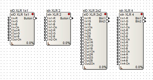
Each module has control pin I/O on the module icon. Two gang devices have twice as many control pin I/O to represent twice as many buttons and LEDs. The I/O names are different for each device to represent the device function.
Each XLR has 4 control inputs to control color and brightness state. Use the properties described above to enable these control pin inputs to control the LEDs. Send a control signal between 0 and 1 to each pin.
Each gang of the device has a single button control output. This is always triggered when pressing the front panel button no matter the configuration of the Button Press Function and Button Hold Function properties. These can be connected to any other control module.
Each Module’s view is similar to the module view for an xIO 4x4 depopulated for I/O not available and with the addition of LED and button state display.
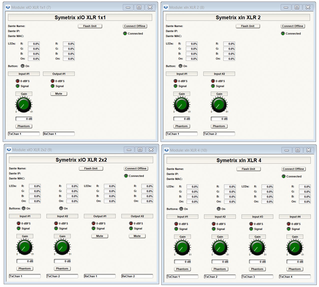
The IO number corresponds to each physical connector according to the table below.
| xIO XLR 1x1 | xIn XLR 2 | xIO XLR 2x2 | xIn XLR 4 | |
| Top Left | Input 1 | Input 1 | Input 1 | Input 1 |
| Bottom Left | Output 1 | Input 2 | Output 1 | Input 2 |
| Top Right | Input 2 | Input 3 | ||
| Bottom Right | Output 2 | Input 4 |
The xIO XLR Intelligent Modules allow all the same presets and remote-control assignment capability as xIO 4x4s and can be export to SymVue.