Feedback Fighters
Where to place feedback fighter
Introduction
Please note that the use of the Feedback Fighter module should always be usedalong with, notinstead of, good system design practice!. Traditional methods such as limiting the number of open microphones, minimizing source-to-microphone distance, positioning microphones and speakers for minimum feedback, and equalizing a room for a flat response should still be employed. The Feedback Fighter can then be used to provide extra gain before feedback, headroom, or control of unwanted feedback. It will not magically fix a poorly designed system or provide gain before feedback beyond the physical limitations of the system.
The Feedback Fighter module automatically detects and suppresses acoustic feedback in an audio system. The module is able to discriminate between feedback and intended audio. When the presence of feedback is detected, a notch filter is added at the frequency of feedback to attenuate it. When first added, the notch attenuates only slightly. If the feedback remains, the notch is deepened as required to eliminate the feedback. A variety of user parameters are available to fine-tune its operation.
Filters can be locked after ring out to prevent them from changing during a performance. The filter settings can also be copied to a dedicated notch filter module, which requires significantly less DSP processing power (for instructions; see Notch Filter below) The filter recycle feature allows filters that haven't been adjusted recently to be slowly released. In this way, filters that may have only been needed temporarily can be removed.
Where to place the Feedback Fighter
Feedback Fighter modules can be placed in a variety of different locations in the signal chain. Each has advantages and disadvantages. You could place the module on a main system output such as a monitor send or the main stereo bus. This has the advantage of requiring the least DSP resources and being the most likely to detect and suppress feedback, regardless of where it occurs. On the other hand, in this location, any notch filters placed will affect all the audio, even sources that would never feed back such as a CD player.
Another possibility is to place a Feedback Fighter module on every input that might feed back. This would usually mean all microphone inputs, or at least all not stationary microphones. The advantage of this approach is that notch filters only have an effect where they are needed and do not interfere with other signals such as CD players. A disadvantage is that more DSP resources are required. Also, consider the scenario where one mic of many is the dominant source of feedback. Ideally only that microphone would be affected by the Feedback Fighter's notch filter. However, if the other non-dominant microphones hear signals very similar to the dominant microphone, they may also detect feedback and notch the audio, somewhat defecting the advantages of independent filtering on each input.
A third method is to use a single Feedback Fighter module on a group of signals. A logical way to do this to create a sub-mix of all potential feedback sources and send this signal through the Feedback Fighter. This method provides the ability to control feedback on multiple mic sources with minimum DSP resources and no affect on other sources. A potential disadvantage is that it may require re-partitioning the mixing and routing of a system to create the potential feedback sub-mix. But when this is possible, this method can be very effective and efficient.
Module Description
There are 8, 16, and 24-notch versions of the Feedback Fighter module. Mono and stereo versions are provided. The stereo module looks for feedback on either input and processes both channels with identical filters to maintain stereo imaging. If independent filtering for each channel is desired, two mono modules should be used instead.
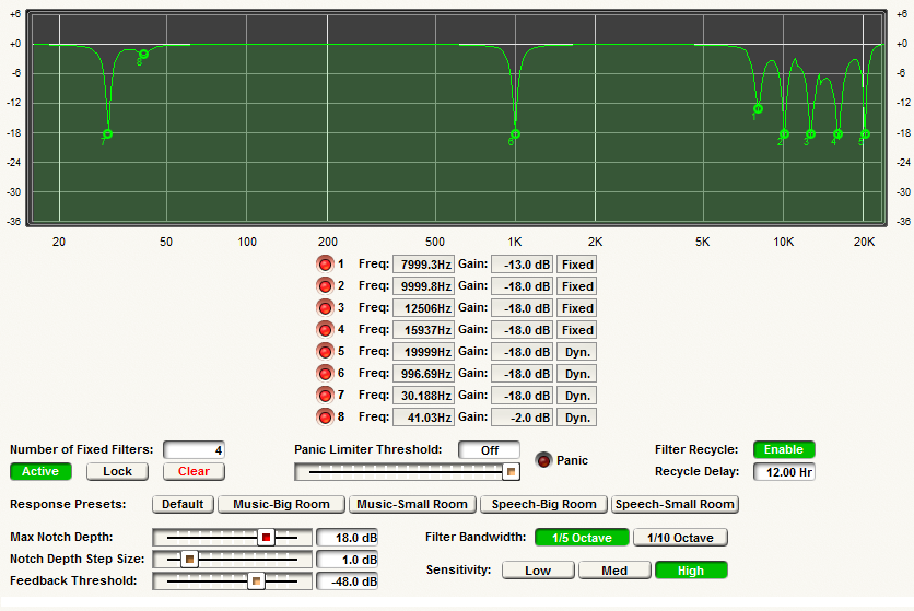
Both mono and stereo version have the following controls:
-
Number of Fixed Filters. Enter a value between zero and the maximum number of filters available in the module. The remaining filters will be dynamic. A fixed filter, once set remains at that frequency until intentionally cleared. A dynamic filter on the other hand may be re-used if all filters have been used and feedback is still occurring. This value defaults to half the number of total filters.
-
Active. Pressing this button activates the notch filters so that filtering is done and the output is affected by the filters present in the feedback fighter module. When the button is not depressed, no new filters can be added, and existing settings can not be adjusted. Deactivating the module does not clear the filters.
-
Lock. When pressed, this prevents the module from adding new filters or changing existing filter settings. When locked Fixed filters will keep their frequency information even after a power cycle. Dynamic filters will be cleared upon a power cycle regardless of the state of the lock button.
-
Clear. Pressing this momentary button clears all filters. Use caution as the filters may be holding back feedback!
-
Panic Limiter Threshold. This parameter tells the module, "Anything above this level is definitely feedback." When the signal is above the feedback threshold, several things occur; a) The output gain is temporarily reduced to control the speed the feedback is building up, b) the output level is limited to prevent run-away feedback, and c) the filter sensitivity increases to more quickly detect feedback. Once the output level decreases to below the threshold, the gain is increased back to unity and the sensitivity returns to normal. This value is a peak level referenced to full-scale digital. Setting it to 0dB defeats the function ("Off" is displayed).
-
Panic LED. This LED lights to indicate that the signal is above the panic limiter threshold and the gain is being reduced. This LED can be assigned to an RS-232/485 controller and read by an external device if desired.
-
Filter Recycle. When enabled, dynamic filters will be slowly released through a programmable time, after they are last set or deepened. If feedback is again detected, the filter will deepen and the clock will start over. This allows filters that are only needed temporarily to be automatically removed. The delay time is set by the Recycle Delay parameter.
-
Recycle Delay. This sets the maximum delay in hours between when a dynamic filter is set or deepened and when it will be slowly released. For this to take effect, Filter Recycle must have been enabled and Lock must be disabled.
-
Max Notch Depth. This set the maximum attenuation any individual notch filter will achieve. While shallower settings may prevent the notches from doing too much "damage", they may also result in worse control over feedback, especially in systems with large narrow resonances.
-
Notch Depth Step Size. This parameter controls how fast the notch is deepened when feedback is detected. If a new feedback frequency is found, the initial filter depth is twice this value. Thereafter, if feedback remains, the notch filter is deepened by this amount at regular intervals. Larger values will cause feedback to be controlled faster. However, too large a value can also cause "over-correction" of the problem. In general, larger rooms should use smaller step sizes. This is because the longer the delay time of the room, the longer it takes for the feedback to go away once the notch is added. Hence, smaller settings help prevent over-correction due to slowly fading out feedback.
-
Feedback Threshold. this parameter tells the module, "Anything below this level is definitely not feedback." This can prevent the module from detecting feedback in soft musical passages or because of low-level hum. Setting too high a value may prevent the module from detecting feedback when it is just starting.
-
Filter Bandwidth. This sets the bandwidth of the notch filters used by the module to either 1/5 or 1/10 octave. The filters used are "constant Q", i.e. they do not widen as they deepen. The wider 1/5 octave setting usually requires fewer filters to achieve the same amount of feedback reduction, but also affects more of the audio spectrum. The narrower 1/10 octave setting is more precise in eliminating feedback frequencies without affecting the rest of the audio, but more notches may be required to eliminate a single resonance. (Ideally, the filter bandwidth should match the width of the resonances it is trying to eliminate.) We suggest using the 1/10 setting for high-fidelity music applications and the 1/5 setting for speech or where the number of filters is limited. This setting is only applied to new filters. If any notches have already been set to attenuate a frequency, the filter will need to be cleared before the bandwidth can be changed.
-
Sensitivity. The most difficult job of the Feedback Fighter is discriminating feedback from intended audio, especially with musical sources. The sensitivity parameter allows trading off of rapid feedback detection and elimination vs. the potential for "false positives", i.e. mistakenly thinking intended audio is feedback. With the Low setting, false positives are minimized but feedback may be detected more slowly. This is useful in music applications or where rapid feedback detection isn't important. With the High setting, anything remotely close to feedback is considered feedback. Hence feedback is detected and suppressed quickly but the chances for false positives are increased. This setting is useful during ring out, or in speech-only applications where no musical signals are ever encountered. The default Medium setting strikes a balance between the above two and is useful in most applications. It is the suggested setting for mixed applications, e.g. speech one day, music the next.
-
Response Presets buttons. These momentary buttons set all the parameters below them. The Default button returns the parameters to their default settings, which are generally appropriate for most applications. The Music-Big Room and Music-Small Room are optimized for music applications in large and small rooms respectively. The Speech-Big Room and Speech-Small Room are optimized for speech-only applications in large and small rooms respectively.
Note: While the Feedback Fighter is designed to work "out of the box" with its default parameters, you can improve the effectiveness of it by giving it hints on the types of signals and environments it will be encountering.
A graph is provided so you can view the frequency response of the filter. You can modify the gain parameters (but not the frequency) by clicking and dragging on the graph. Drag the green box vertically to adjust the amount of attenuation. If you drag the gain all the way back to zero, the filter becomes unused and is available to be redeployed if feedback is detected.
Note: Normally all filters are cleared whenever a download is performed. If you want to preserve fixed filters you can "Lock" the number and frequency of the fixed filters. Also if you want to save the filters, you can save them using the Save Module Settings right click option, download and then restore them using Load Module Settings. These settings can also be copied to a notch filter module as described below.
To retain settings through power cycles, use the "Lock" button to retain fixed filters. use the "Last known operating state" feature. This can be found under Tools/Site Preferences.
How to use the Feedback Fighter
The Feedback Fighter can either be used to ring out a system during sound check or as an ongoing preventative measure during normal operation.
Ring Out
If you require maximum gain before feedback, use this procedure to ring out the system:
-
With the system gain turned down, remove any existing filters using the Clear button.
-
Set the various module parameters to the desired values. To more quickly detect and suppress feedback, set the Sensitivity to High. Using a low Panic Limiter Threshold is also recommended so that the level of the feedback is reduced.
-
Open all mics and slowly increase system gain until feedback occurs. Stop increasing while the Feedback Fighter notches the feedback.
-
After the feedback disappears, continue increasing the gain.
-
Repeat until the desired gain is reached or all fixed filters are assigned.
-
Change the Sensitivity setting to the appropriate value for your application. Change the Panic Limiter threshold to something just above the maximum expected non-feedback signal level.
At this point, the module can be locked if desired, or remain unlocked to deal with any feedback that may occur during performance. Another possibility is to copy the settings to a notch filter module (see the section on the Notch Filter for more information). This can provide reduced DSP resources or the ability to add even more filters.
Preventative instructions
The Feedback Fighter can work effectively if your system is generally stable and free from feedback but you want to ensure feedback doesn't occur due to operator error or unexpected mic movement. Simply set the parameters to appropriate values, make sure all filters are cleared and go. If you are using the module to protect your speakers, it is recommended you follow it with a compressor/limiter module for additional protection. A limiter with appropriate settings will ensure speakers are not damaged even if all notch filters are used up or the Feedback Fighter is unable to control the feedback (e.g. system gain is dramatically too high).
Notch Filter
The Notch Filter module attenuates chosen frequencies to remove feedback issues within a system. Unlike Feedback Fighter modules, the attenuation and frequencies are manually set. After 'ringing out' a system with a Feedback Fighter, to save on DSP resources, it is possible to replace it with a Notch Filters.
Note: The Filter Bandwidth setting is only applied to new filters. If any notches have already been set to attenuate a frequency, the filter will need to be cleared before the bandwidth can be changed.
Copying Feedback Fighter settings to a Notch Filter:
-
Right-click on the Feedback Fighter and select the 'Copy Module Settings' option.
-
Right-click on the Notch Filter that will replace the Feedback Fighter and select the 'Paste Module Settings' option.
-
Replace the Feedback Fighter with the Notch Filter in the audio path.