Acoustic Echo Canceller
This page is in reference to using acoustic echo cancellation with either a Radius AEC or a 4 Channel AEC Input Card installed in an Edge, Radius AEC, or Radius 12x8 EX DSP. For acoustic echo cancellation with the Radius NX, go here.
Module Specification and Features
Using the Module for Noise Reduction Only
Introduction
Acoustic Echo Cancellation, or AEC, is a digital audio signal processing technique used in audio and video teleconferencing when conversation takes place between people in a local conference room and one or more callers located at a distance from the local room. The AEC process serves to enhance intelligibility for the distant callers by removing echoes acoustically generated in the local room.
Consider the scenario of a remote loudspeaker on a standard telephone handset, conferencing into a large room with one or more loudspeakers and microphones (see diagram below). As the remote or "far end" party speaks, the audio comes out the loudspeakers, and is then picked up by the microphones, which sends that audio back to the far end. The result is the far end caller hears an echo of his or her own speech. This can make communication difficult, especially with longer round-trip delays. An acoustic echo canceller (AEC) is used to provide intelligible, echo-free audio for the far end caller by reducing or eliminating the echo of his own voice.
Acoustic echo canceller (AEC) with noise reduction block diagram:
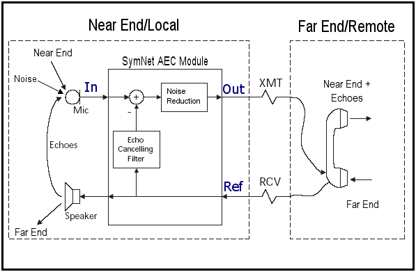
The Symetrix AEC algorithm removes far end audio picked up by local microphones. It also reduces noise picked up by the microphones in the local room. This echo-free signal is then sent back to the far end.
Composer features a multi-channel, adaptive filter-based acoustic echo cancellation (AEC) algorithm which requires less processing power than previous methods. AEC can be added to any Symetrix installation with the addition of the 4 Channel AEC Input Card which is compatible with the Symetrix Edge, Radius AEC, or Radius 12x8 EX. The 4 Channel AEC Input Card also features NLP (non-linear processing), automatic gain control (AGC), and noise cancellation.
Note: Example designs are available in the Composer folder on the C drive.
Module Specifications and Features
The Symetrix AEC is based on technology licensed from DSP Algorithms (www.dspalgorithms.com). Some of the features include:
-
Superior and consistent single-talk echo reduction of 60dB in any acoustic environment.
-
Proprietary robust and effective double talk detector.
-
Echo reduction of 20dB or more during double-talk periods.
-
Instant full convergence to 60dB echo reduction in 100 milliseconds, or less. Rate of adaptation is fast enough to allow excellent performance even with moving microphones and dynamic gain changes.
-
Supports multiple microphones (up to 4 inputs per card/module, 16 per unit, fully loaded)
-
Supports routing any audio through the AEC algorithm using the AEC Aux input
-
Independent Ref input for every channel of AEC
-
Low algorithm processing latency, 11ms
-
Noise cancellation algorithm providing up to 20 dB background noise reduction. Noise reduction level is user adjustable.
-
The algorithm is effective against moderate non-linearitites in the acoustic response model and Reference signals.
-
Consistent performance in all acoustic environments, from a small room with a reverberation time of less than 100ms to a large conference hall with reverberation time of 1.5 seconds or more.
-
Suitable for any application that requires echo and/or noise cancellation; including speaker-phones, audio and video conferencing, desktop conferencing, voice over IP, Internet phones and many others.
-
Fully configurable. System designers have complete control over system switches and algorithm parameters, including the ability to enable/disable and set the target level of individual channels in any functional block.
-
Fully compliant with the G.167 standard.
Input Considerations
Composer provides an 'AEC Ins' module, 'AEC Refs' module, and 'AEC Auxes' module from the installation and configuration of the Edge unit with the 4 Channel AEC Input Card or when a Radius AEC is used in a Composer design. The AEC algorithm removes echo and noise from each input individually based upon the signal that is routed into the corresponding 'AEC Refs' input. Each AEC input offers an AEC out for sending to the far end and a direct out (unprocessed, zero latency) for local microphone reinforcement.
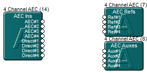
The 4 Channel AEC Input Card’s 'AEC Ins' module provides 4 AEC outputs and 4 direct outputs. AEC outputs are the microphone input signal post the AEC algorithm, minus any acoustical echo, but incurring 11ms latency. Direct outputs are the microphone input signal dry, unprocessed, and with no latency caused by the AEC algorithm. Typically the direct outputs are used for local reinforcement of the near end microphones.
The 4 Channel AEC Input Card’s 'AEC Refs' module provides 4 reference inputs to the AEC algorithm, where the reference signal will be removed from the corresponding “AEC Ins” module AEC output. This signal would typically be the voice from the far end.
The 4 Channel AEC Input Card’s 'AEC Auxes' module provides 4 auxiliary inputs used for routing audio through the AEC algorithm without the need for the desired source to be physically plugged into the AEC card’s analog input. As an example, the 'AEC Auxes' could be used to provide AEC to a wireless Dante enabled microphone where the mic audio enters the DSP via Dante, and the output of the Dante channel is connected to an 'AEC Auxes' input.
In the past, echo cancellation was very expensive, therefore, often a single channel of acoustic echo cancellation was used on a mix of microphones. However, each microphone "hears" a slightly different version of the signal from the loudspeakers based on its position, orientation, nearby reflective surfaces, etc. If the mix of microphones was dynamically adjusted, for example with an automixer, the echo canceller was forced to constantly adapt to the changing input signal and continually re-converge. When the AEC algorithm was forced to re-converge due to a dynamically changing input signal, typically it resulted in AEC artifacts such as a flanger type effect on the audio and/or brief bits of echo getting through to the far end caller.
In a situation where two or more microphones are mixed statically and they share an acoustical space, it is possible to connect the mix of microphones to a single 'AEC Auxes' input. When any dynamic adjustments are made during operation, it is ideal to use one channel of AEC processing for each microphone and/or have the microphone(s) which require the AEC connected directly to the 4 Channel AEC Input Card’s analog input.
The Symetrix AEC algorithm is extremely fast at converging, 11ms which means the AEC algorithm will be effective with roving microphones and dynamically mixed signals. Using a dedicated echo canceller per input is the ideal; however, if a dedicated AEC input per microphone is not feasible given the budget constraints of the A/V design, the Symetrix AEC algorithm can be used on a microphone mix using the 'AEC Auxes' module input. The superior convergence speed of the Symetrix AEC algorithm and dedicated SHARC processor of the 4 Channel AEC Input Card makes it an effective solution for even the most demanding AEC application.
Signal Flow
Any adjustments, dynamics processing, EQ filtering, or speaker delay that are applied to the audio routed to the local loudspeakers, must also be made to the same audio routed to the 'AEC Refs' module’s input. For example, the reference should be routed post any gain control or AGC module used on the far end audio prior to the local reinforcement, so that the 'AEC Refs' input source is identical to the audio being routed to the analog outputs/local sound reinforcement. The AEC algorithm always needs to "be aware of" any changes made to the audio being amplified in the conference room in order for the AEC algorithm to effectively remove this audio from the 4 Channel AEC Input Card’s analog input. The diagram below illustrates the correct and incorrect ways of routing the reference to the 'AEC Refs' input.
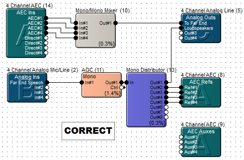
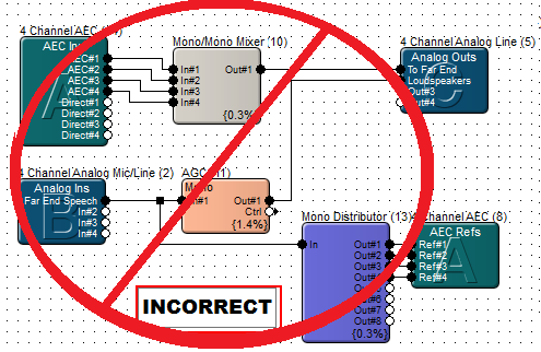
The same principle applies to adjusting the amplifier gain, active loudspeaker's gain, or using in-wall speaker attenuators: don't do it. If the end user requires manual adjustment of the room level, use a gain control module upstream from the AEC Reference input. The very fast rate of adaptation and convergence of the Symetrix AEC algorithm often allows it to gracefully deal with doing things "incorrectly".
Inputs and Outputs
-
AEC#1,AEC#2, etc.- These are the connections for the local microphone inputs post the AEC algorithm. For the greatest degree of echo cancellation with the least amount of convergence, it is recommended that each microphone be connected to the 4 Channel AEC Input Card and each microphone should use its own dedicated channel of AEC processing.
-
Direct#n- These are the connections for the local microphone inputs without AEC. The audio is dry, unprocessed, with zero latency added by the AEC algorithm.
-
Ref#n- This is the connection for the reference signal, the audio that needs to be removed from the microphone input and prevented from being passed along to the far end. Whatever audio is connected to this input is the audio the AEC algorithm will cancel out. This may be audio from a telephone hybrid, or other tie-line to the remote location and is often the same signal that is sent to the loudspeakers. If the intention is to use the 4 Channel AEC Input Card’s analog input or aux input for noise reduction only, leave this input unconnected.
-
Aux#n- These inputs are used for routing any audio through the AEC algorithm to remove acoustical echo without having a source connected to the physical inputs of the 4 Channel AEC Input Card’s analog input. The signal placed into these inputs can be a statically mixed bus of multiple microphones, a single mic routed into the DSP over Dante, or a source in which noise cancellation is desired.
Note: The AEC inputs are configured to freeze the coefficients automatically when there is no signal.
Connection Diagrams
The diagrams below show the typical connections associated with the use of AEC in Composer enabled product. Five different scenarios are shown in order of increasing complexity. In all cases, the far end is assumed to be connected through the Symetrix 2 Line Analog Telephone Interface Card. The same designs would apply if another mechanism was used for the audio connection (ISDN, Dante, VOIP, analog tie-line, 3rd party telephone hybrid, etc).
Diagram #1: AEC system without local reinforcement of the microphones
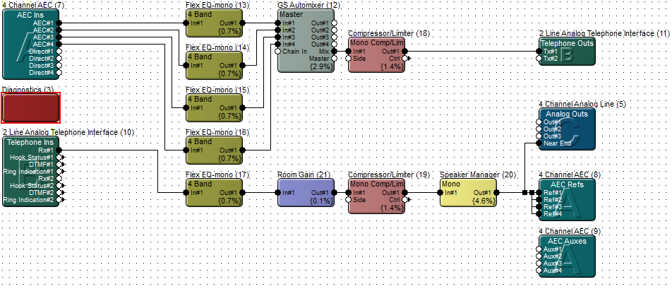
This diagram shows the simplest AEC signal path where there is no need to amplify the local microphones. The microphones are automixed and sent to the far end only.
This design would be appropriate for small conference rooms with very few participants and functions similar to a deluxe speaker phone.
Note: The ‘AEC Refs’ input and analog output feeding the local reinforcement both receive the exact same signal routed post any room gain adjustments and loudspeaker processing.
Diagram #2: AEC system with local reinforcement of media inputs excluding the microphones
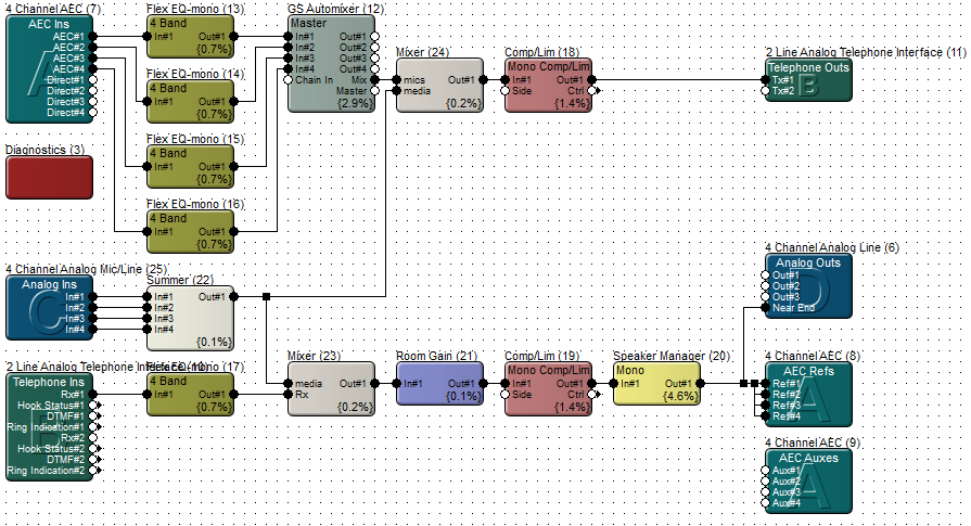
This diagram shows an AEC signal path where local media sources need amplification; however, there is no need to amplify the local microphones. The microphones are automixed and sent to the far end only.
This design would be appropriate for small conference rooms with very few participants that is also used as a presentation room.
Note:
- The ‘AEC Refs’ input and analog output feeding the local reinforcement both receive the exact same signal routed post any room gain adjustments and loudspeaker processing.
- Media sources are routed directly to the far end; however, since they are also amplified in the local conference room the media inputs are also included in the Reference signal to avoid “doubling” the media audio content when it is picked up by the local microphones and mixed with the audio transmitted to the far end caller. If the media audio is “doubled” the far end may hear comb filtering.
Diagram #3: AEC system with local reinforcement of the microphones
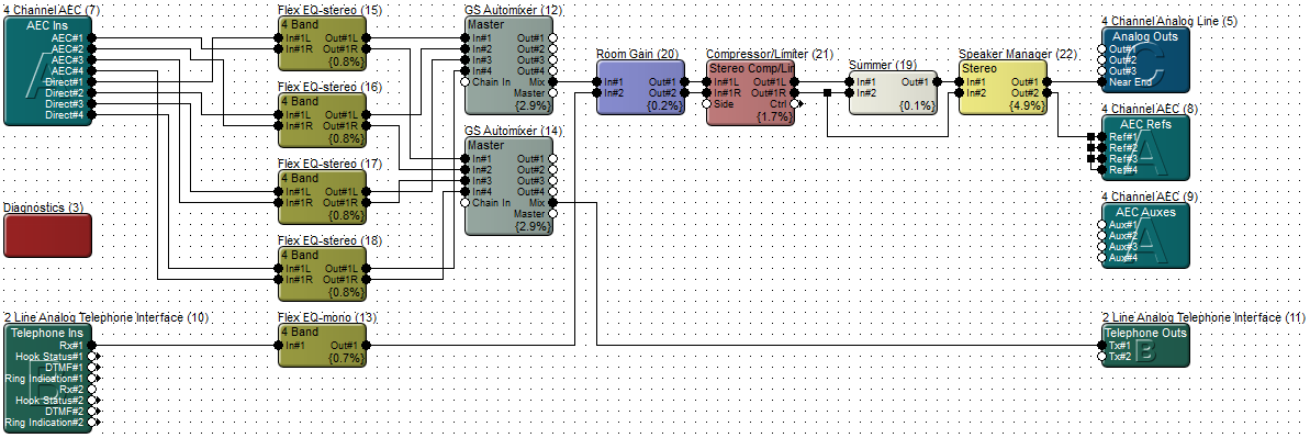
This diagram shows an AEC signal path where the local microphones are amplified by the local sound reinforcement and also sent to the far end caller.
This design would be appropriate for medium sized conference rooms where amplifying the local microphones is necessary for everyone in the conference room to hear the other attendees speak.
Note:
-
The Ref input and analog output feeding the local reinforcement do not receive the exact same audio, although the audio to both are routed together through any room gain adjustments and loudspeaker processing.
-
The local reinforcement (near end) receives the (direct) microphones and the incoming phone signal (far end). The Ref input only receive the incoming phone signal (far end).
Diagram #4: AEC system with local reinforcement of the microphones in a mix-minus configuration
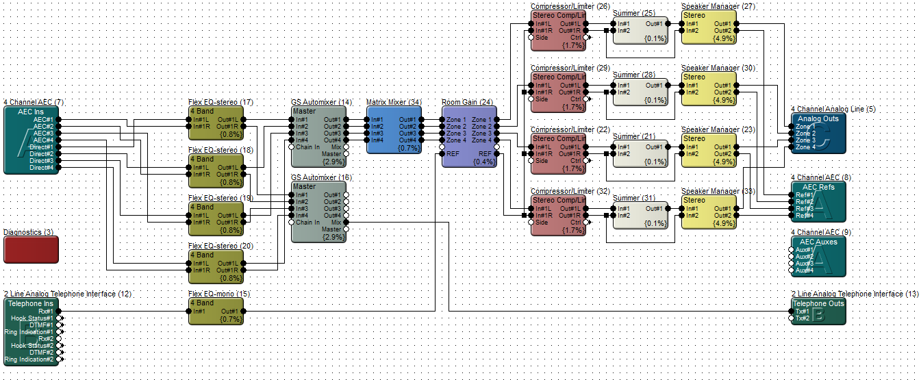
This diagram shows an AEC signal path where the local microphones are amplified by the local sound reinforcement in a mix-minus configuration and also sent to the far end caller.
This design would be appropriate for medium to large sized conference rooms where amplifying the local microphones is necessary for everyone in the conference room to hear the attendees speak; however, in order to maximize gain before feedback or if loudspeaker placement relative to the microphone placement is not ideal, a mix-minus configuration of the microphones may be necessary.
Note:
-
The ‘AEC Ins’ module AEC outputs are automixed and routed to the far end only.
-
The ‘AEC Ins’ module Direct outputs are automixed and routed to the local reinforcement. Direct outputs do not incur the 11ms latency of the AEC algorithm.
-
The direct outputs of the local microphone automixer are connected directly to a Matrix Mixer for mix-minus routing.
-
The Matrix Mixer outputs and Reference signal are routed through the same Room Gain module so that a room level adjustment affects all zones and the ‘AEC Refs’ inputs equally.
-
The local reinforcement receives the local microphones and the far end caller audio; however, the ‘AEC Refs’ inputs receive only the far end caller. This is important so that the AEC algorithm does not cancel out the near end caller from the audio sent to the far end.
-
Gain adjustments and loudspeaker processing is applied to the locally reinforced audio and the reference equally.
Diagram #5: AEC with local reinforcement of the microphones in a mix-minus system, media inputs, and 3rd party Dante enable wireless mics needing AEC.
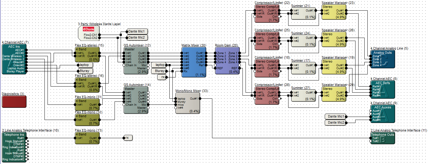
This diagram shows an AEC signal path where the local microphones are amplified by the local sound reinforcement in a mix-minus configuration and also sent to the far end caller. Additionally, there are two Dante enabled wireless microphones that are routed through the AEC algorithm using the “AEC Auxes” module. The left over analog inputs of the 4 Channel AEC Input Card is used for two media sources.
This design would be appropriate for medium to large sized conference rooms where amplifying the local microphones is necessary for everyone in the conference room to hear the attendees speak; however, in order to maximize gain before feedback or if loudspeaker placement relative to the microphone placement is not ideal, a mix-minus configuration of the microphones may be necessary.
Note:
-
The ‘AEC Ins’ module AEC outputs are automixed and routed to the far end only.
-
The ‘AEC Ins’ module Direct outputs are automixed and routed to the local reinforcement. Direct outputs do not incur the 11ms latency of the AEC algorithm.
-
The direct outputs of the local microphone automixer are connect directly to a Matrix Mixer for mix-minus routing.
-
Two Dante enabled wireless microphones are routed into the DSP via Dante. They directly connect to the local automixer for local reinforcement and are also routed through the 'AEC Auxes' module input 3 and 4 before being sent to the far end caller echo-free.
-
The left over ‘AEC Ins’ Direct output for channel 3 and 4 is used as the analog input for the two media sources.
-
The Matrix Mixer outputs and Reference signal are routed through the same Room Gain module so that a room level adjustment affects all zones and the ‘AEC Refs’ inputs equally.
-
The local reinforcement receives the local mics, media audio, and the far end caller audio; however, the ‘AEC Refs’ inputs receive only the media audio and the far end caller. This is important so that the AEC algorithm does not cancel out the near end caller from the audio sent to the far end.
-
Media sources are routed directly to the far end; however, since they are also amplified in the local conference room the media inputs are also included in the Reference signal to avoid “doubling” the media audio content when it is picked up by the local microphones and mixed with the audio transmitted to the far end caller. If the media audio is “doubled” the far end may hear comb filtering.
-
Gain adjustments and loudspeaker processing is applied to the locally reinforced audio and the reference equally.
Using the Module for Noise Reduction Only
It is possible to use the AEC modules for noise reduction only. Simply leave the 'Ref In' input unconnected, and turn off the Echo Cancellation Enable button.
Controls
-
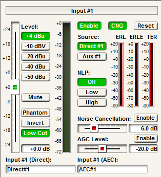
AEC Enable- Engaging this button enables/disables the acoustic echo cancellation algorithm. In most applications this button will be engaged, unless the AEC module is being used for noise cancellation or performing an 'A/B' test of AEC On and Off.
-
CNG- Comfort Noise Generator; this button enables/disables the comfort noise generator. The CNG adds in some noise during silences to let the far end know the call is still connected.
-
Reset- Resets the AEC algorithm forcing it to re-converge completely from zeroed out values. Additionally this button resets the AEC meters such as ERL, ERLE, and TER. Toggling 'AEC Enable' freezes the algorithm at the current values or starts the algorithm with the most recent readings. Only "Reset" will fully purge all readings from the AEC algorithm. The reset key on any given channel will reset the convergence on every channel on the card.
-
Level(+4 dBu, -10 dBV, -20 dBu, -40 dBu, -50 dBu radio buttons) - Determines the gain applied by the microphone preamplifier stage. Set this according to the nominal level of the source. The input stage is designed around a nominal input level of +4 dBu balanced with 20 dB of headroom. In other words, a signal of +24 dBu balanced will generate 0 dBFS. The level buttons apply 0, 11.8, 24, 44, and 54 dB of gain respectively so that signals arriving at the inputs at the specified levels will all be the same +4 dBu level following the microphone preamplifier.
-
Source- This selection determines which source will be routed through the AEC processing. Direct will apply AEC processing to the AEC analog input. Selecting Aux will apply the AEC processing to the signal which is routed to the 'AEC Auxes' module.
-
ERL- Echo Return Loss; The difference in signal level between the audio which is present at the Reference input and the audio measured in the room by the microphones. A negative value indicates a positive loss and demonstrates good AEC system performance. Target is 0 to -18dB.
-
ERLE- Echo Return Loss Enhancement; The amount the AEC algorithm was able to reduce the echo.
-
TER- Total Echo Reduction; The sum of ERL and ERLE. Echo reduction introduced by the room acoustics (ERL), and the AEC algorithm (ERLE).
-
Non-linear Processing- A fancy ducker that works to remove any residual echo that the AEC algorithm missed. Excessive NLP can adversely affect double-talk operation. There are 3 settings; Off, Low and High.
-
Mute– Mutes the Direct and AEC Inputs.
-
Phantom- When depressed, turns on +48 VDC phantom power for the analog input’s mic pre-amp.
-
Invert- Engage this button to change the polarity of the audio signal by 180°, similar to the phase button found on many analog consoles.
-
Low Cut- Engage this button to implement a 4th order, 24dB/Octave High Pass Filter at 100Hz. Frequencies below 100Hz will be attenuated at a rate of 24dB/Octave. Frequencies above 100Hz will pass unaffected.
-
Noise Cancellation- The level of attenuation implemented on constant room noise.
-
AGC Level- Automatic Gain Control: Takes signals of indeterminate levels up to a target RMS output level while maintaining program dynamics.
Notes on DSP Usage
All channels of AEC in Edge and Radius AEC execute wideband acoustic echo cancellation (20Hz to 20KHz) implemented by a 400MHz SHARC processing chip present on the input card itself. This means that using AEC does not deplete DSP resources managed by the Symetrix site file.
Double-Talk Considerations
Double-talk is the condition when both the far and near end are talking at the same time. This is the most difficult scenario for an echo canceller to deal with. When this condition occurs, the AEC algorithm may not achieve as much echo reduction and even miss small portions of the acoustic echo. NLP automatically will reduce the far end double-talk when it occurs. The NLP suppression is adjustable from Off, Low, and High so that the NLP suppression can be set to an acceptable level determined by the nature and severity of the double-talk artifacts. Excessive NLP can adversely affect the near and far end signals making them sound flat, lifeless and even slightly distorted.
Glossary of Terms
AEC- Acoustic Echo Cancellation. The term "acoustic" refers to the fact that the echo to be cancelled is created by acoustic reflections in a physical space. It is used to distinguish this from the echo cancellers used in phone systems, which are similar in principle but only cancel electronically generated echoes.
Single-talk- The case where only one party is speaking. This represents the majority of most conversations and is the easiest case for an echo canceller to handle.
Double-talk- The case where both parties are speaking at the same time. This is the most difficult case for an echo canceller to manage.
Reference signal (Ref)- This is the signal that the echo canceller is trying to remove from its inputs. Typically, this is the same signal that is being sent out the loudspeakers in the local room, or the component of that signal that is generated at the far end. See also FES.
FES- Far End Speech. This is the speech signal from the remote caller. This signal is generally sent out through a loudspeaker on the near-end and then is picked up by the microphones on the near-end. This pick-up is what needs to be cancelled by the echo canceller. This is also sometimes called the reference signal, reference input, or 'Ref'.
NES- Near End Speech. This is the speech signal from the local talker, which includes a bleed component (the echo) from the Reference or FES signal. This signal is processed by the echo canceller to remove the Reference component.
RES - Residual Speech. This is the output signal from the echo canceller. It consists of the NES signal with the Reference/FES component subtracted out and/or noise removed.
Appendix A: Set-up Tips; How to get the most out of Symetrix AEC
The relative signal levels at the main inputs and reference input are important. We have found that the best results are achieved when the signal level of the Ref In is slightly higher (6-12dB) than local inputs as measured when only the far end is speaking. It may be useful to add a gain module immediately before the AEC to adjust these levels.
Just as with most other audio problems, the best way to deal with the problem of acoustic echo is in the acoustic domain, rather than trying to deal with the issues using DSP. AEC is not a substitute for proper gain structure, or the proper placement of the microphones and loudspeakers.
The first goal of an installation should be to minimize the amount of far end pickup and noise and maximize the amount of local speech in the microphones. In doing so, the AEC and noise reduction will not need to work as hard and will give much better results. Of course, there are always conflicting goals (aesthetics, costs, physical size constraints) that may make this difficult, but acoustic optimization will improve communication.
Tips for setting up AEC to achieve the best results:
-
Dampen the acoustic environment to reduce reflections from the wall, floor, ceilings, etc. Sometimes spending a little in this area can save a great deal in equipment costs.
-
Position microphones to minimize pick-up from loudspeakers. For example, in a room with a high ceiling, flush-mounting microphones in the ceiling will put them very close to ceiling speakers and very far from the people speaking. Whenever possible avoid ceiling mics in all conferencing applications. Table -top boundary, gooseneck microphones and lapel microphones work well because they are typically close to participant's mouths and far from loudspeakers. Understandably, some people prefer ceiling mounted microphones to minimize cabling and clutter on a conference table. If ceiling microphones are used, position them as far away from loudspeakers and as close to meeting participants as possible. We recommend using a directional microphone pointing away from loudspeakers and hanging down as low as practical to get closer to participants.
-
Use enough microphones and be mindful of placement in order to give even coverage to all participants.
-
Position microphones as far away as possible from noise sources such as lap tops, projector fans, HVAC, etc.
-
Use as low a level as possible of the far end audio amplified in the local room. Of course it needs to be clearly audible throughout the room, but the softer it is, the less echo the AEC algorithm will have to cancel.
-
Use enough loudspeakers and be mindful of placement in order to give even coverage throughout the listening audience. Doing so, will allow for a lower volume level at each loudspeaker, resulting in less echo to cancel in the program material.
-
Coach meeting participants to speak in a clear voice directly into the nearest microphone.
The above goals may be difficult, or impossible to fully achieve, especially when retrofitting an existing room. Every step taken helps to improve the AEC performance, which in turn improves the over-all audio experience.
Appendix B: Comparison of Echo Canceller Techniques
Composer offers both Echo Reduction and Echo Cancellation. Echo reduction is provided by the Echo Reducer in the conferencing modules section of the toolkit. Echo cancellation is provided by the Symetrix 4 Channel AEC Input Card and internally in the Radius AEC. This section will discuss some of the differences between echo reduction and echo cancellation.
There are two main strategies for reducing echo in conferencing applications:
- Dynamic gain modification (sometimes called non-linear processing, gain sharing or gating)
- Adaptive filtering
Many speaker-phones use the first technique, often with a simple gate. Composer offers a Gain-sharing Echo Reducer based upon this principle. The Symetrix Echo Reducer module provides a much more smooth and natural operation than a traditional echo reducer which employs a gate. The employment of the Echo Reducer module works well for moderate amounts of echo, or applications where for the majority of the time only one talker is speaking at a time. For more demanding installations, adaptive filtering is preferred. The AEC algorithm running on the 4 Channel AEC Input Card and Radius AEC is a next-generation adaptive filter.
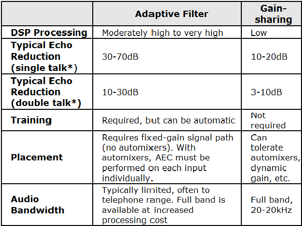
* See the glossary for definitions of these and other terms.
In most cases, the adaptive filter-based echo cancellers are preferred. The gain sharing echo reducer is recommended when using AEC is not feasible and the echo problem is moderate.