Control Logics
These modules allow you to process Boolean control signals in a variety of ways. The 2-26 input logic modules, decoders, encoders and multiplexers perform logical operations on the input signals (traditionally referred to as combinatorial logic). With these modules, the output depends only on the current inputs. The Delays Logic, Counter and Flip-Flop modules deal with sequencing of control signals and events (traditionally referred to as sequential logic). With these modules, the output depends on both current inputs and past inputs. This class of modules gives you the capability to build complex decision making logic and create sequences of events.
Input Logic Modules
There are logic modules that have 2, 4, 8, or 16 inputs. These logic modules perform Boolean logic operations (and, or exclusive or) on various numbers of inputs. The modules have two outputs labeled, True and False. The True output will be 100% when the logic function is True. the False output is always the opposite of the True output (negative logic) Any input less than 50% is assumed to be 0, or false. Any input greater than or equal to 50% is assumed to be (1), or True. For each input, there is an enable button. When turned on, the corresponding input will affect the output. When turned off, the input will be ignored. By turning off inputs, functions of other numbers of inputs such as 3, 5, 6 etc. can be generated.
The modules can perform one of (4) different logical operations; And, Or Xor and On. The And function is True only if all enabled inputs are True. The Or function is True if any one of the enabled inputs is True. The Xor function is True if any odd number (1, 3, 5) of enabled inputs are True. Note: If all inputs are disabled, the Xor and Or functions will be false and And function will be True. The On function is always true regardless of the state of the inputs. (On may be useful to generate a constant 100% control signal). By using the False output, you can create the inverse function, i.e. Nand, Nor, XNor, or Off. Truth tables are show below for the 2- and 4- input versions to illustrate this. The tables for the large input versions are too large to show, but can be extrapolated from the examples below.
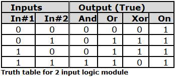
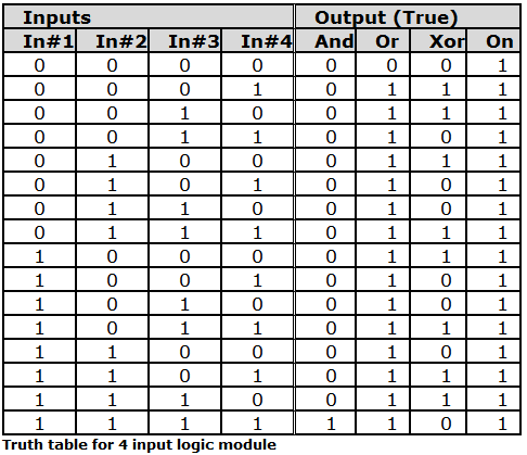
Note: 0 = false or 0%, 1 = True or 100%. If the False output is used substitute 0 for 1 and vice versa for all outputs. The tables assume all inputs are enabled.
Controls:
-
Logic Function (AND, OR, XOR, ON buttons). Sets the logic function implemented by the module. See above for a description of each logic function.
-
Enable buttons (per input). Determines whether the corresponding input is included or ignored in the logic function. If the Enable button is turned off for an input, that input will have no effect on the output.
Input LEDs indicate the state of each input. Two output LEDs (True and False) indicate the result of the logic function. If the True LED is on, then the True output will be 100% and the False output will be 0%. If the False LED is on, then the True output will be 0% and the False output will be 100%.
Binary Decoder Modules
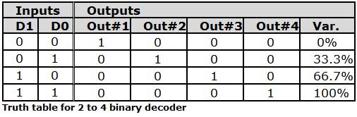
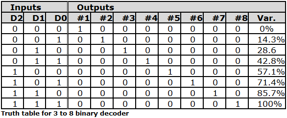
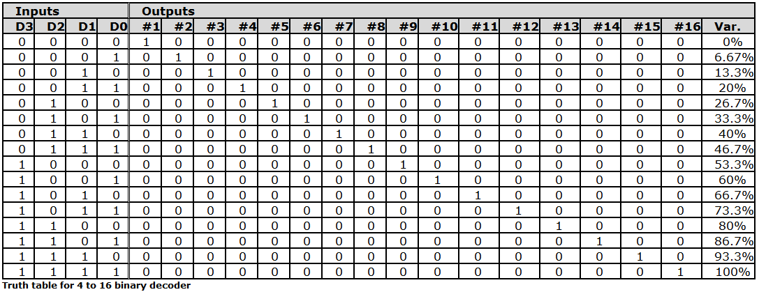
There are three different binary decoder modules: 2 input to 4 output, 3 input to 8 output and 4 input to 16 output. Each one looks at its binary inputs and turns on exactly one output that corresponds to the binary value of the inputs. There is also a variable control output that takes on a value between 0 and 100% base on the binary value of the inputs. Any input less than 50% is assumed to be 0 or false. Any input greater than or equal to 50% is assumed to be (1) or true.
A text display indicates the binary value represented by the inputs. The truth tables below indicate the outputs for all combinations for inputs.
Multiplexer Modules
There are four different multiplexer modules: 2 input to 1 output, 4 input to 1 output, 8 input to 1 output, and 16 input to 1 output. Each one acts like a switch or selector and routes a selected input to the output. The selection is made with a continuous control signal input. All inputs can be continuous or Boolean control signals. This module can be thought of as an input selector for control signals. Use it when you need to select between multiple control sources to control a single parameter. There are no controls for these modules.
A text display indicates the input select signal control value and also which input it is selecting. A text display also indicates the output value.
4-bit Binary Encoder
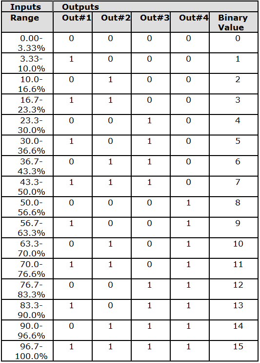
This module takes continuous control signal input and outputs a binary value based on the input level. It can be thought of as a crude analog to digital converter for control signals. It may be useful when you have a continuous control signal but need to control a binary parameter the table below shows the output values for various ranges of inputs.
Flip-Flop
This module implements a toggle flip-flop. Each time the Trigger input transitions from 0 to 1, the output toggles from 0 to 1, or vice versa. Reset and Set inputs cause the flip- flop to be forced to a 0 or a 1 respectively. Two outputs are provided, Q and NOT Q. The Q output is the true or positive logic output and the NOT Q output is always the inverse of the Q output. The truth table below shows the operation of the flip-flop for various inputs.
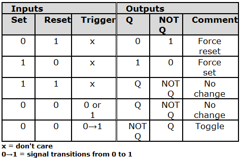
For the set and reset inputs, any input less than 50% is assumed to be 0, or False. Any input greater than or equal to 50% is assumed to be 1 or True. For the trigger input, hysteresis is used. If the signal is 0, the signal must rise above 51% to be considered a 1. If it is 1, it must fall below 49% to be considered a 0. This helps prevent multiple triggers on a slowly changing noisy signal.
Buttons are also provided to force a trigger, set, or reset. These buttons have the same effect as the control signals with the same name. The buttons override anything the control signals are doing.
Controls:
-
Force Trigger. Manually triggers the flip-flop, causing it to toggle.
-
Force Set. Manually sets the flip-flop, causing it to go to the set state (Q=1).
Note: if this button is turned on externally via RS-232/485, the flip-flop will be held in set until the remote control explicitly turns it off again (by sending a zero control value).
- Force Reset. Manually resets the flip-flop, causing it to go to the reset state (Q=0).
Note: If this button is turned on externally via RS-232/485, the flip-flop will be held in set until the remote control explicitly turns it off again (by sending a zero control value).
- *Text displays indicate the levels of the three inputs. Two LEDs indicate the states of Q and NOT Q outputs. Only one will be on at a give time.
Counter
This module implements an event counter. The counter increments each time the Trigger input transitions from 0 to 1. After the counter reaches a user-specified threshold count, the output will go True indicating the threshold count has been reached. A Reset input causes the counter to be forced to 0. This module may be useful in counting the number of occurrences of error conditions or triggering another event after a specified number of events has occurred.
For the reset inputs, any input less than 50% is assumed to be 0 or false. Any input greater than or equal to 50% is assumed to be 1 or true. For the trigger input, hysteresis is used. If the signal is 0, the signal must rise above 51% to be considered a 1. If it is 1, it must fall below 49% to be considered a 0. This helps prevent multiple triggers on a slowly changing noisy signal.
Buttons are also provided to force a trigger, or reset the counter. These buttons have the same affect as the control signals with the same name. The buttons override anything the control signals are doing.
Controls:
-
Force Trigger. Manually triggers the counter, causing Count to increment.
-
Force Reset. Manually resets the counter, causing Count to go to zero.
** Note: If this button is turned on externally via RS-232/485, the flip-flop will be held in set until the remote control explicitly turns it off again (by sending a zero control value).**
- Threshold. Sets the value that causes the Boolean Output to go True. When Count = Threshold, the Output = 100%, otherwise it is 0%. Click in the text entry box and specify a numerical value from 1 to 2147483647.
Text displays indicate the levels of the two inputs A LED indicates the state of the output.
Note: the counter will wrap back to zero after it reaches 2,147,283,647.
Delay Logic
This module allows for various sequencing tasks such as delaying a control signal, extending the length of a pulse, creating simple event sequencers, and creating a low frequency oscillator. It has two outputs that go high for programmable times after the module is triggered. A loop mode allows the module to repeat it's sequence, effectively creating a square-wave oscillator.
The module is triggered by a control signal that goes from a level of 49% or below to a level of 51%, or above. Once triggered, the module enters the Delay state. While in this state, the Triggered output is 100% After the programmable Delay Time has passed, the module enters the Hold state. In this state, the Hold output will go to 100% and stay that way for the programmable Hold Time. If the Allow Re triggering button is depressed, the delay count will be reset on each trigger that happens during the Delay state. Triggers during the Hold state will have no effect until the Hold Time has elapsed.
The Loop Mode control allows the Delay Logic Module to be used as a low frequency square-wave oscillator with programmable on and off times (i.e. programmable duty cycle. After it is triggered once, it will continue to cycle between the Delay and Hold states until the Reset button is pushed. When operating as an oscillator, Allow Re triggering should be turned off.
For the trigger input, hysteresis is used. If the signal is 0, the signal must rise above 51% to be considered a 1. If it is 1, it must fall below 49% to be considered at 0. This helps prevent multiple triggers on a slowly changing noisy signal.
Buttons are also provided to force a trigger, or reset the module. The force trigger button has the same effect as the Trigger control signal.
Controls:
-
Force Trigger. Manually triggers the module, causing it to enter the Delay state.
-
Delay Time. Time in seconds that the module waits after being triggered before entering the Hold state. Adjust using the slider or click in the text entry box to specify a numerical value. When the module is used as an oscillator, this is the time for which the Delay output will be 100% and the Hold output will be 0%.
-
Hold Time. Time in seconds that the module remains in the Hold state. Adjust using the slider or click in the text entry box to specify a numerical value. When the module is used as an oscillator, this is the time for which the Delay output will be 0% and the Hold output will be 100%.
-
Reset. Manually resets the module immediately, regardless of what state it is in. Both outputs will be 0% following a reset.
** Note: If this button is turned on externally via RS-232/485, the flip-flop will be held in set until the remote control explicitly turns it off again.**
-
Loop Mode. When depressed, the module will go immediately into the Delay state after it finishes the Hold state. Otherwise, it will go to the Reset state. Turn this setting on to use as an oscillator.
-
Allow Re triggering. When depressed, while the module is in the Delay state, additional triggers will cause the delay timer to start over just as if it was entering the delays state again. when not depressed, additional triggers during the Delay state are ignored.
Text displays indicate the level of the input. LEDs indicate the states of the outputs. to create more complex sequences of events, multiple Delay Logic modules can be chained together.
Connect the Hold output to one module to the Trigger input of the next.
Example: programmable fade in and out with program change. The delay logic module can be used to generate a simple sequence of events that fades out an audio source, switches between programs, and fades back in every time button is pushed.
Every time the Delay Logic module is triggered, the Triggered output goes high. This signal is inverted and set to the Ramp Processor to generate a fade-out. The Delay time determines how long the delay is before the program changes. The Ramp Processors Down Rate determines the fade out length and is set to match the Delay Time. After the Delay time has elapsed, the Hold output goes high, triggering the Flip-Flop to change states. The Flip-Flop output controls the Selector, causing it to switch programs. At the same time, the Ramp processor begins to fade back in, with a fade in time controlled by the Up Rate. This set-up allows the flexibility of different fade in and fade out times and/or the ability to fade out, then pause for a programmable length of time before fading back in.