xControl External Control Expander
Features:
- External control expansion device for use with Symetrix Edge and/or Radius DSP systems for cost-effective additional push-to-talk capability and LED activity indication in conferencing and paging applications.
- 8 analog control inputs may each be configured for 1 potentiometer or 2 switches. 16 logic outputs drive LEDs or trigger external relays.
- 2 RS-232 ports interface with peripherals such as projectors, camera controls and lighting. Multiple xControls combine for unlimited flexibility.
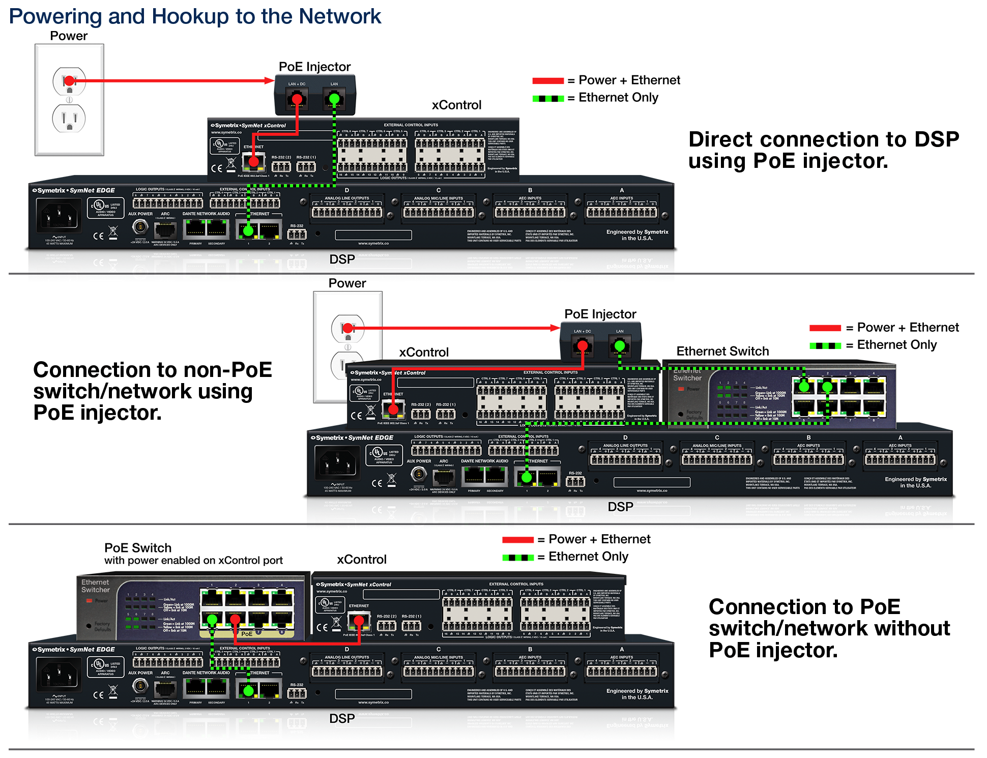
- xControl utilizes Power over Ethernet (PoE) for a single cable connection to a PoE switch, or, a direct connection to the DSP (PoE injector included).
- Simple set-up and management using Composer open architecture software.
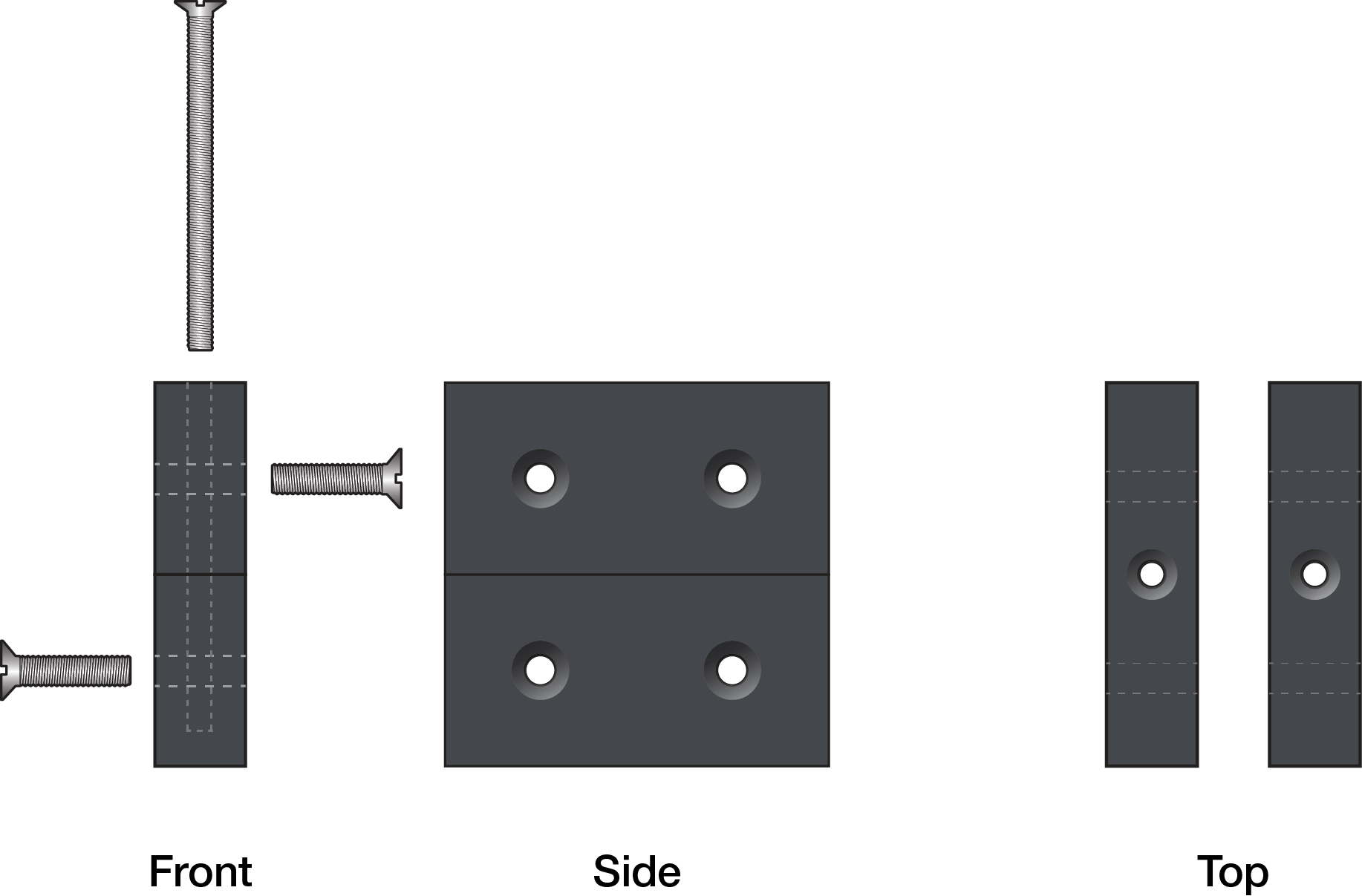
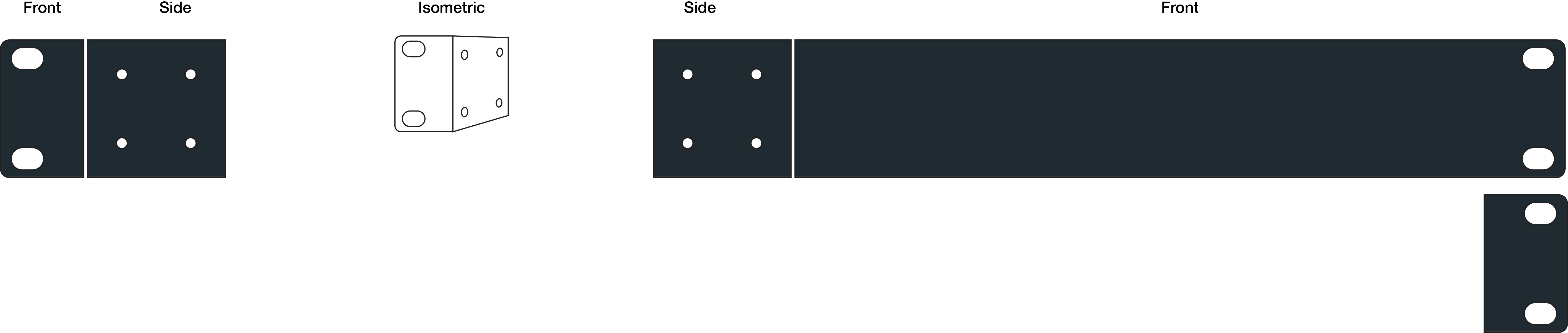
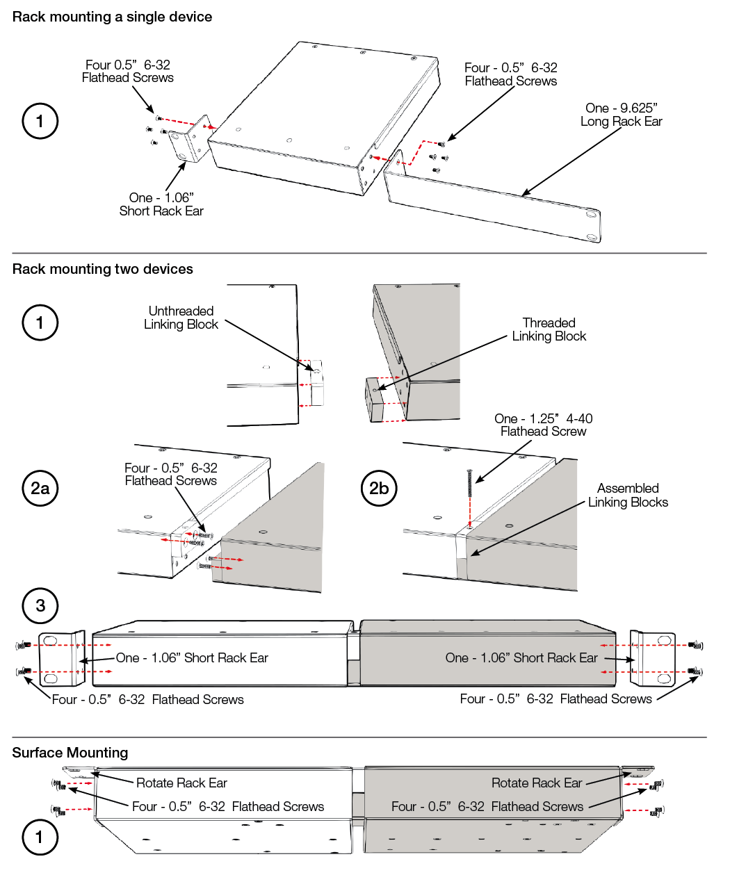
- Versatile half-rack design. All hardware is included to mount 1 or 2 in a single rack space or to surface mount.
Specifications
System
Ethernet Cable: Standard CAT5/6, maximum device-to-device length = 328 feet / 100 meters
External Control Inputs
Number of External Control Inputs: Eight (8) to sixteen (16) total; each configurable to accommodate one (1) potentiometer or two (2) closures for a maximum of 8 potentiometers or 16 closures
Connectors: 3.81 mm terminal blocks
Reference Voltage: 3.3 VDC
Recommended Potentiometer: 10k Ohms linear taper
Logic Outputs
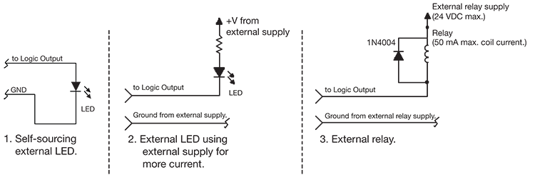
Number of Logic Outputs: Sixteen (16); each capable of driving an LED directly, triggering an external relay or sinking external voltage/current. Low (0 VDC) when active, pulled high (5 VDC) when inactive
Connectors: 3.81 mm terminal blocks
Maximum Output Voltage: 5 VDC
Maximum Output Current: 10 mA
Maximum External Power Supply Voltage: 24 VDC
Maximum External Power Supply Current Sinking: 50 mA
RS-232 Ports
Number of RS-232 Ports: Two (2)
Connectors: 3.81 mm terminal blocks
RS-232 Output Parameters: 57.6 kbaud (default), 8 data bits, 1 stop bit, no parity, no flow control wired straight-through, only pins 2, 3, and 5 required
Mechanical Data
Space Required
Half rack unit (WDH: 20.83 cm x 22.86 cm x 4.37 cm / 8.2 in. x 9 in. x 1.72 in.) Depth does not include connector allowance.
Allow at least 3 inches additional clearance for rear panel connections. Additional depth may be required depending upon specific wiring and connections.
Electrical
PoE IEEE 802.3af Class 1, 6 Watts maximum. No line voltage switching required.
Ventilation
Maximum recommended ambient operating temperature is 30 C / 86 F. Ensure that the left and right equipment sides are unobstructed (5.08 cm, 2 in. minimum clearance). The ventilation should not be impeded by covering the ventilation openings with items such as newspapers, tablecloths, curtains, etc.
Certifications or Compliance
Safety: UL 60065, cUL 60065, IEC 60065
EMC: EN 55103-1, EN 55103-2, FCC Part 15
Environmental: RoHS
Shipping Weight
2.0 kg (4.4 lbs.)
A&E Specifications
The half rack device shall provide logic I/O expansion for a Symetrix system with eight to sixteen total external control inputs, sixteen logic outputs, and two RS-232 ports.
Each external control input shall be configurable to accommodate one potentiometer or two closures for a maximum of eight potentiometers or sixteen closures. Each logic output shall be capable of driving an LED directly, triggering an external relay or sinking external voltage/current, low (0 VDC) when active, pulled high (5 VDC) when inactive.
All logic I/O and RS-232 connections shall be accessed via rear panel 3.81 mm terminal block connectors.
System connection for configuration and communication shall be via the device’s rear panel Ethernet connector.
A designer software application shall be provided that operates on a Windows computer, with network interface installed, running Windows® 7 or higher operating system.
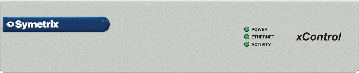
The front panel shall include indicators for POWER, ETHERNET and ACTIVITY. The device shall be powered over Ethernet (PoE) by an IEEE 802.3af Class 1 standard compliant switch or the included injector. The device shall meet UL/CSA and CE safety requirements and comply with CE and FCC Part 15 emissions limits. The device shall be RoHS compliant. The chassis shall be constructed of cold rolled steel, and may be surface mounted or mount into a standard 19” 1U EIA rack. The device shall be aSymetrix xControl.
Front Panel
| Item | Comments |
|---|---|
| Power | The power LED flashes green until the unit fully boots. If the LED remains flashing indefinitely, this may indicate a firmware or hardware problem. The power LED will be solid green when operating normally. |
| Ethernet | The bi-color LED flashes green briefly when a Symetrix-related packet is received, including communication from Composer software. If the LED is solid green it indicates constant network communication. One exception relates to the Access Code (hardware security). If the access code is invalid, the Ethernet LED flashes red instead of green. The Ethernet LED will not flash for other types of network traffic such as ping, FTP, DHCP negotiations, Telnet, etc. The LEDs on the rear-panel surrounding the RJ-45 connector react to every type of network traffic. In DHCP mode, during boot the Ethernet LED is amber when the device first queries the network for a DHCP IP address. The query can last up to 15 seconds. If the unit is assigned a DHCP IP address, the Ethernet LED will flash green for 1 second, and then enter the normal mode of flashing when a Symetrix packet is received. If the unit is not assigned a DHCP IP address, the Ethernet LED will flash amber for 1 second, then default to a class B IP address of 169.254.#.# before entering the normal mode of flashing when a Symetrix packet is received. The Ethernet LED flashes red for 1 second when the Ethernet cable is removed and flashes green for 1 second when the Ethernet cable is inserted. |
| Activity | The Bi-color LED flashes green with any logic input activity, flashes red with any logic output activity, and flashes amber with any RS-232 input or output activity. |
Rear Panel
| Item | Comments |
|---|---|
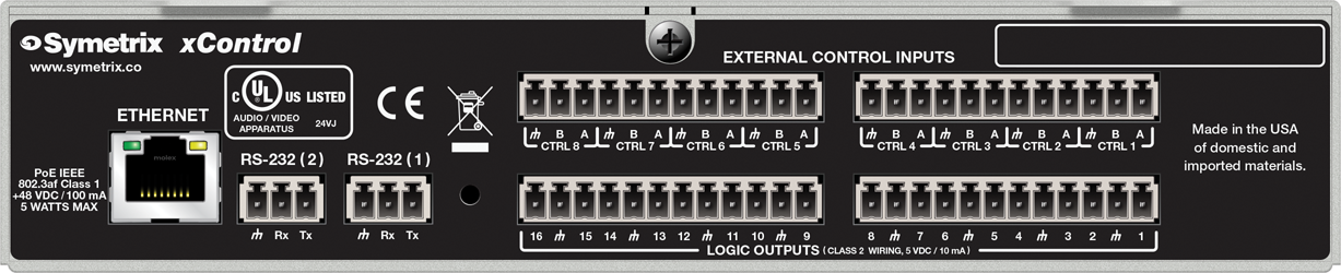
| Ethernet | 10/100 Base-T Ethernet port for network connection to the Symetrix system over IP. Features auto-crossover sensing for direct device-to-device connections. Accepts PoE IEEE 802.3af Class 1. |
| RS-232 | Two serial communications interface for sending strings to 3rd party devices or accepting 3rd party control commands. Port Settings: 57.6 kbaud (default), 8 data bits, 1 stop bit, no parity, no flow control. |
| External Control Inputs | Eight (8) analog control inputs. Each analog control input can be configured to support 1 potentiometer or 2 closures (+3.3 VDC reference voltage supplied). |
| Logic Outputs | Sixteen (16) logic outputs with eight (8) paired common ground pins. Logic Outputs go low (0V) when active, and are internally pulled high (5V) when inactive and can drive external LED indicators directly. |
Mounting
Single Unit Assembled

Dual Unit Assembled

Hardware
External Control Input Wiring
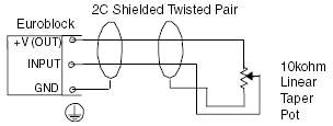
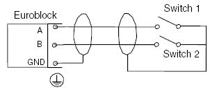
The following illustrations show the connection of either a 10k ohm linear potentiometer, a mechanical rotary encoder, or switches, to one of the external control inputs of the xControl.
Typical Control Potentiometer Wiring
Typical Control Switch Wiring for Discrete Switch Inputs
Typical Mechanical Rotary Encoder Wiring
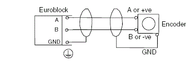
The Symetrix model RC-3 is the recommended potentiometer for the xControl. Suitable potentiometers, switches, and encoders can be sourced from electronic parts suppliers. Note that encoders must be of the mechanical type.
Logic Output Wiring
The Logic Outputs may drive external LEDs, control external relays, or trigger external switchers. The Logic Outputs go low (0V) when active, and are internally pulled high (5V) when inactive. Connect to the Logic Outputs as shown in the following diagrams:
External Control Protocol
The xControl acts as an intermediary RS-232 input and output device for an EDGE or Radius system. All incoming commands except for the following are passed directly to the host DSP.
Flash Unit
Command:
FU \
The Flash Unit command can be used to confirm communication to the xControl. If successful, the three LEDS on the front of the unit will flash simultaneously between green and red. For a complete list of commands, please refer to the Composer Control Protocol.
Hook Up Diagrams