Control Processes
These modules allow you to process continuous control signals in a variety of ways. The inverter, detectors, scaling, and taper modules allow changing the amplitude characteristics of control signals while the ramp processor allows changing their dynamic characteristics. A comparator module allows for comparing control signals.
Inverter
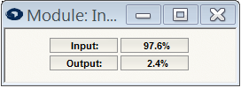 This module takes a control signal and outputs the inverse of it. Given an input signal that ranges from 0 to 100%, the output equation would be; output = 100% - input. This module operates equally well on continuous and boolean control signals. For Boolean signals it functions like a logical inverter. Text displays are provided showing the level of the input and output.
Threshold Detector
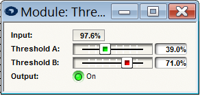
This module outputs a Boolean signal based on whether the input control signal is above or below a threshold. The threshold is specified in two parts, as a Threshold A and a Threshold B, to allow for hysteresis. If the input signal is above both thresholds, then the output is on. If the input signal is below both thresholds, then the output is off. If the input falls between the thresholds, then the output remains at its previous state. This module may be useful in cleanly converting a noisy continuous control signal to a Boolean control signal.
Controls:
-
Threshold A. Determines the level above which the detector is On. Adjust using the slider or click in the text entry box to specify a numerical value.
-
Threshold B. Determines the level below which the detector is Off. Adjust using the slider or click in the text entry box to specify a numerical value.
A LED indicates whether the input is above or below the thresholds. The module has two outputs, True and False. When the output is on, the True output is 100% and the False output is 0%. When the output is off, the True output is 0% and the False output is 100%. In other words, the False output is True output inverted.
Note: For clarity, it is advisable to set the A Level above the B Level. However, the module will still function the same way if this is not the case.
Range Detector
This module outputs a bi-level signal based on whether the input control signal is within a specified range or not. The range is specified with a low and high threshold. The two levels for the output signal are independently programmable. If the input signal is between the two thresholds, then the output will be In Range level. If the input signal is not between the two thresholds, then the output will be the Out of Range level.
Controls:
-
Lo Threshold. Determines the level above which the input signal must be to be considered In Range. Adjust using the slider or click in the text entry box to specify a numerical value.
-
Hi threshold. Determines the level below which the input signal must be in order to be considered In Range. Adjust using the slider, or click the text entry box to specify a numerical value.
-
In Range Output Level. Determines the level that will be output when the input signal is within the range specified by the low and high thresholds. Adjust using the slider or click in the text entry box to specify a numerical value.
-
Out of Range Output Level. Determines the level that will be output when the input signal is outside the range specified by the low and high thresholds. Adjust using the slider, or click in the text entry box to specify a numerical value.
-
In Range. LED which indicates whether the input is In Range, or not.
Note: For clarity, it is adviseable to set the Lo Threshold parameter below the Hi threshold parameter. However, the module will still function properly even if this is not the case.
Scaler
This module performs linear scaling of a continuous control signal. It maps a range of input values to a range of output values. it is very useful to limit the maximum and minimum value of a parameter controlled by a control signal.
Controls:
-
Input Lo Level. If the input signal is less than or equal to this value, the output will be the Output Lo level. Adjust using the slider or click in the text entry box to specify a numerical value.
-
Input Hi Level. If the input signal is greater than or equal to this value, the output will be the Output Hi level. Adjust using the slider or click in the text entry box to specify a numerical value.
-
Output Lo Level. Sets the level of the output when the input signal is less than or equal to the Input Lo Level. Adjust using the slider or click in the text entry box to specify a numerical value.
-
Output Hi Level. Sets the level of the output when the input signal is greater than or equal to the Input Hi Level. Adjust using the slider or click in the text entry box to specify a numerical value.
** Note: To generate an inverse characteristic where the output goes down when the input goes up, set the output low level **
-
above the output high level.*
-
*Text displays indicate the levels of the input and output.
Linear to Log Taper
This module performs non-linear scaling of a continuous control signal. It converts a linear input signal into a logarithmic output (linear in dB). It may be useful in controlling a logarithmic parameter from a linear source.
Controls:
-
Log Range. Controls the shape of the logarithmic curve. Large values for this parameter allow a wide range of logarithmic control. Small values for this parameter give more precise control but over a smaller range. This setting, along with the Mute on Zero Input button, heavily affects the behavior for low-level inputs. Set this parameter according to the range of control you want to allow. Adjust using the slider or click in the text entry box to specify a numerical value.
-
Mute on Zero Input. When this button id engaged, a zero input will result in a zero output. If not engaged, a zero input will result in an output equal to minus the log range. When controlling a gain, turn this on if you want to allow the control signal to completely mute the audio.
Text displays indicate the levels of the input and output. A graph shows the characteristic curve.
Linear to Audio Taper
This module performs non-linear scaling of a continuous control signal. It converts a linear input signal to an audio taper (pseudo-logarithmic) output. It may be useful in controlling a logarithmic parameter from a linear source. Audio taper differs from log taper in that audio taper moves faster for low level inputs. It mimics a mixing console fader that has compressed scale near the bottom of its range an is linear in dB everywhere else. Technically, a linear taper is used for low-level inputs (<15%) and a log taper is used for the rest of the range. This curve can be best visualized on the graph by turning the Log Range control all the way down.
Controls:
- Log Range. Controls the shape of the audio taper curve. Large values for this parameter allow a wide range of control. Small values for this parameter give more precise control but over a smaller ranger before rapidly dropping to zero. Set this parameter according to how much range of control you want to allow. Adjust using the slider or click in the text entry box to specify a numerical value.
Text displays indicate the levels of the input and output. A graph shows the characteristic curve.
Log to Linear Taper
This module performs a non-linear scaling of a continuous control signal. It converts a logarithmic (linear in dB) input signal to a linear output. It may be useful in controlling a linear parameter from a logarithmic source.
Controls:
- Log Range. Controls the shape of the logarithmic curve. Large values for this parameter allow a wide range of logarithmic control. Small values for this parameter give more precise control but over a smaller range. Set this parameter according to the characteristic of the logarithmic input source and how much range of control you want to allow. Adjust using the slider or click in the text entry box to specify a numerical value.
Text displays indicate the levels of the input and output. A graph shows the characteristic curve.
Linear to Custom Taper
This module performs programmable scaling of continuous control signal using (8) independent linear segments. It converts a linear input signal to an arbitrary custom-shaped output. it may be useful in creative control signal applications.
The taper can be controlled by clicking and dragging on the (8) handles on the graph. The first and last angles are locked horizontally to the 0% and 100% boundaries respectively but may be moved vertically. the middle (7) points may be moved both horizontally and vertically.
Controls:
-
Node Input. Controls the x coordinate of the selected node. Adjust by dragging the node on the graph or click in the text entry box to specify a numerical value.
-
Node Output. controls the y coordinate of the selected node. Adjust by dragging the node on the graph or click in the text entry box to specify a numerical value.
Text displays indicate the levels of the input and output. A graph shows the response curve characteristic of the parameters.
Ramp Processor
This module allows controlling of the dynamic characteristics of a control signal. It can be used, for example, to convert an abrupt on-off transition to a smooth fade out. Also, it can be used to smooth control signals in a non-linear fashion by only responding to large changes and ignoring small ones. It may be useful when slow, controlled fades are required, or in other creative control signal applications.
Controls:
-
Difference Threshold. Sets the amount that the input-output difference must exceed before the output is changed. In other words, if the difference between the input and output is less than this amount, the output remains constant. If the difference exceeds this amount, then the output will begin to move to match the input at the programmed rate. Setting the parameter to 0% bypasses this function and causes the output to always try to track the input. Using a larger value may be useful in filtering noisy control signals. The Difference display may be useful in setting this parameter. Adjust using the slider or click in the text entry box to specify a numerical value.
-
Up Rate. Sets the response speed used when the output signal is increasing. This time is the time it would take the output to go from 0% to 100%. If the required movement is smaller, the actual time will be proportionally less. Adjust using the slider, or click in the text entry box to specify a numerical value.
** Note: the Up and Down rates can be linked by enabling the Link button.**
-
*Down Rate. Sets the respo0nse speed used when the output signal is decreasing. This time is the time it would take the output to go from 100% to 0%. If the required movement is smaller, the actual time will be proportionally less. Adjust using the slider or click in the text entry box to specify a numerical value. *
-
Link button. When depressed, links the Up Rate and Down Rate parameters so adjusting either parameter moves both parameters. This button has no effect if the Up Rate and Down Rate parameters are controlled externally. If external linking is desired, assign the same hardware controller to both the Up Rate and Down Rate parameters.
-
Shape (Linear, Log, Audio buttons). Sets the shape of the curve along which the output travels. In Linear mode, the output moves linearly until it matches the input. In Log mode, the output moves logarithmically (linear in dB) until it matches the input. In Audio mode, the output moves linearly for low levels and logarithmically (linear in dB) for high levels until it matches the input. Audio, or Log mode are useful when using the control signal to create long, smooth fades.
-
*Active. When engaged the ramp function is inserted into the audio path and affects the signal. *
Text displays indicate the levels of the input, output and difference between them.
Comparator
This module compares the two control signals labeled Input A and Input B and indicates if they are less than, greater than, or equal there are (3) Boolean outputs to indicate the comparison status; A>B, A=B, A\<B. Exactly one of these will be at on (100%) and the other two will be at off (0%).
Text displays indicate the levels of the two inputs. Three LEDs indicate the relationship of the inputs. Only one will be on at a given time.