Edge Frame


Symetrix Edge scalable hardware partners with Composer open architecture software for total design synergy. Networked audio connections use Dante protocol for ultra low latency (when Dante Card installed). Multiple end user control options complete the system.
Features:
- Four configurable I/O card slots, up to 16 channels total of local I/O plus 128 (64x64) channels of Dante network audio (when Dante card installed).
- Eight logic inputs (or four analog control inputs) and eight logic outputs.
- Redundant Dante network audio ports.
- Dual Ethernet ports for configuration and control, and RS-232 for third party control systems.
- ARC port for Symetrix ARC wall panel remotes.
- Port for optional redundant external power supply.
- Internal gigabit switch that eliminates the need for an external switch in many systems. Systems using 10 or more Edge mainframes and/or mainframes separated by distances over 100 meters can be implemented with off-the-shelf gigabit hardware.
Specifications
System
Processors: 1 x Analog Devices SHARC 21489 @ 400 MHz SIMD
Raw processing capacity: 400 MIPS, 1.6 GFLOPS
Sampling Rate: 48 kHz, ± 100 ppm
Frequency Response (A/D/A): 20 Hz – 20 kHz, ± 0.5 dB
Dynamic Range (A/D/A): > 114 dB, A-weighted
Channel Separation (A/D/A): > 108 dB @ 1 kHz, +24 dBu
Latency (A/D/A): 0.88 mS, inputs routed to outputs
Delay memory: 174 mono seconds
Analog control inputs: 0-3.3 VDC
Recommended external control potentiometer: 10k Ohm, linear
Logic outputs: Low (0V) when active, pulled high (5V) when inactive
Logic output maximum external power supply voltage: 24 VDC
Logic output maximum external power supply current sinking: 50 mA
Logic output maximum output current: 10 mA
RS-232 accessory serial I/O: 57.6 kbaud (default), 8 data bits, 1 stop bit, no parity, no flow control wired straight-through, only pins 2, 3, and 5 required
RS-485 serial I/O: 38.4 kbaud (default) 8 data bits, 1 stop bit, no parity, no flow control. May be broken out of ARC port
Ethernet Cable: Standard CAT5, maximum device to device length = 100 meters
Dante Cable: Standard CAT6, maximum device to device length = 100 meters
ARC Cable: Standard CAT5, distance dependent upon load and number of devices
Maximum stored presets: 1000
*** For complete audio I/O performance specifications, refer to the individual I/O cards' documentation.
Mechanical Data
Space Required
1U (WDH: 18.91 in x 9.5 in x 1.72 in / 48.02 cm x 24.13 cm x 4.37 cm). Depth does not include connector allowance.
Allow at least 3 inches of additional clearance for rear panel connections. Additional depth may be required depending upon your specific wiring and connections.
Electrical
100-240 VAC, 50/60 Hz, 45 Watts maximum, universal input, and/or suitable 24 VDC / 2.0 Amp auxiliary power source. No line voltage switching required.
Ventilation
Maximum recommended ambient operating temperature is 30 C / 86 F. Ensure that the left and right equipment sides are unobstructed (5.08 cm, 2 in. minimum clearance). The ventilation should not be impeded by covering the ventilation openings with items such as newspapers, tablecloths, curtains, etc.
Certifications or Compliance
Safety: UL 60065, cUL 60065, IEC 60065
EMC: EN 55103-1, EN 55103-2, FCC Part 15
Environmental: RoHS
Shipping Weight
13 lbs. (5.9 kg)
A&E Specifications
The device shall provide four I/O card slots accepting any combination of available cards providing up to (16) channels of local I/O. All signal processing, mixing and routing functions (including I/O levels) shall be controllable via software. Audio inputs and outputs shall be accessed via rear panel 3.81 mm terminal block connectors. Some I/O cards may utilize other connector types.
Network audio expansion shall be provided by a factory installed optional Dante card with a capacity of 128 (64x64) channels. Primary and Secondary Dante network audio connections shall be provided for redundant network implementation. Connectors shall be gigabit RJ45 utilizing CAT6 cable.
A designer software application shall be provided that operates on a Windows computer, with network interface installed, running Windows® 7 or higher operating system. Computer connection for configuration shall be via the device’s rear panel Ethernet connector. All internal processing shall be digital (DSP). Available DSP components shall include (but not be limited to) various forms of: mixers, equalizers, filters, crossovers, dynamics/gain controls, routers, delays, remote controls, meters, generators, onboard logic, and diagnostics.
The front panel shall include input and output signal level indicators, I/O card type indicators as well as indicators for POWER, ARC, RS-232, NETWORK, and DANTE (PRIMARY and SECONDARY). Additionally, a front panel LCD shall display certain system parameters as well as allow editing of network parameters and may be programmed as an ARC for custom user control via the front panel UP, DOWN, LEFT, RIGHT and ENTER buttons.
External control shall include dedicated software screens as well as preset selection, I/O level control and muting using the optional ARC wall panel remote controls via industry-standard CAT5 cable with RJ45 connectors. A built-in web server shall provide four instances of ARC-WEB, which allows for user control from nearly any web browser or mobile device. Logic I/O shall consist of eight contact closure or four potentiometer inputs along with eight logic outputs. The logic outputs may be used to drive LEDs directly or control external relays or switchers. All program memory shall be non-volatile and provide program security should power fail. The device shall provide an on board real time clock to facilitate automatic, timed changing of presets and may sync to NTP. Third-party control systems may interface over IP and RS-232 using a published ASCII control protocol.
Audio conversion shall be 24-bit, 48 kHz and internal processing shall be 32-bit or 40-bit floating point, 48 kHz.
The device shall have an IEC power input socket for 120-240 VAC and a captive power input socket for an external 24 VDC supply. The device shall meet UL/CSA and CE safety requirements and comply with CE and FCC Part 15 emissions limits. The device shall be RoHS compliant. The chassis shall be constructed of cold rolled steel and moulded plastic, and mount into a standard 19” 1U EIA rack. The device shall be aSymetrix Symetrix Edge.
Front Panel
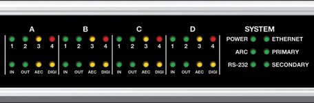
| Item | Description | Comments |
|---|---|---|
| Signal Level LEDs (Top Row) | Four banks of four (16 total) Bi-color LEDs | Illuminates green to indicate signal present > -26 dBu (> -50 dBFS), amber between +4 dBu (-20 dBFS) and +22 dBu (-2 dBFS) and red to indicate clipping > +23 dBu (> -1 dBFS). All signal level LEDs will briefly flash amber on configuration load (on boot or when Composer pushes to hardware). |
| Card Type LEDs (Bottom Row) | Four banks of four (16 total) LEDs, two green then two amber. | Indicates I/O card type with combination of LEDs. For example, The "IN" LED only indicates a 4 Channel Analog Input card, while an "OUT" LED with a "DIGI" LED indicates a 4 Channel Digital Output card. |
| Power | Bi-color LED | Flashes green until the unit fully boots. If it remains flashing indefinitely, this may indicate a firmware or hardware problem. Solid green when operating on the main power input. The Power LED flashes green/amber to indicate a fan failure. |
| ARC | Bi-color LED | Bi-color LED turns solid green when any physical RS485 ARC device is connected (ARC-2e, ARC-K1e, etc.). Turns amber briefly whenever an ARC, physical or virtual (ARC-WEB, ARC-FP, ARC-K1e, etc.), communicates with the device. |
| RS-232 | Bi-color LED | Bi-color LED flashes green when there is any RS-232 data activity. Turns amber briefly whenever a parameter is changed. |
| Ethernet | Bi-color LED | The bi-color LED flashes green briefly when a Symetrix-related packet is received, including communication from Composer software. If the LED is solid green it indicates constant network communication. One exception relates to the Access Code (hardware security). If the access code is invalid, the Ethernet LED flashes red instead of green. The Ethernet LED will not flash for other types of network traffic such as ping, FTP, DHCP negotiations, Telnet, etc. The LEDs on the rear-panel surrounding the RJ-45 connector react to every type of network traffic. In DHCP mode, the unit will adopt a 169.254.x.x address when the cable is plugged. It will retain this address until it receives one from a DHCP server. If it doesn't receive one in 15 seconds, the LED will flash amber for 1 second, but continue to use the 169.254 address and continue to request an address from a DHCP server. If the unit is assigned a DHCP IP address, the Ethernet LED will flash green for 1 second, and then enter the normal mode of flashing when a Symetrix packet is received. The Ethernet LED flashes red for 1 second when the Ethernet cable is removed and flashes green for 1 second when the Ethernet cable is inserted. |
| (Dante) Primary | Bi-color LED | Bi-color LED is off when nothing is connected or no Dante card installed, green when connected and all subscriptions are working, amber when some subscriptions working, and red when no subscriptions working. If a name conflict is detected, both the Primary and Secondary Dante LEDs will flash red. A name conflict means that 2 units were found on the network with the same name. |
| (Dante) Secondary | Bi-color LED | Bi-color LED is off when nothing is connected or no Dante card installed, green when connected and all subscriptions are working, amber when some subscriptions working, and red when no subscriptions working. If a name conflict is detected, both the Primary and Secondary Dante LEDs will flash red. A name conflict means that 2 units were found on the network with the same name. |
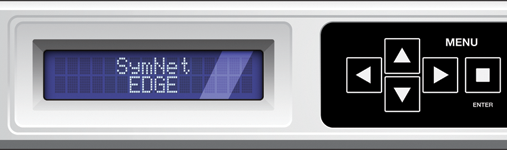
| Item | Description | Comments |
|---|---|---|
| Display | 16 character by 2 line text display. | Displays system status, menus and messages. |
| Menu Buttons | Five (5) momentary buttons (Up / Down / Left / Right / Enter) | For navigation of System parameters and ARC-FP programming. |
***For more information on the Display and Menu Buttons, refer to the Front Panel UI topic.
Front Panel UI
Overview
The front panel user interface consists of System Status LEDs, I/O Level LEDs, a 5-way switch consisting of discreet UP, DOWN, LEFT, RIGHT and ENTER buttons, and a 16 character by 2 line display.
This topic details the functionality provided by the 5-way switch and display.
The front panel UI may function in one of three ways at any point in time:
- As an ARC-FP (Front Panel). The ARC-FP provides end-user or installer control over a pre-determined (as programmed by the contractor) set of parameters in a menu-driven fashion nearly identical to the ARC-2e or ARC-WEB controllers. ARC-FP enabling/disabling and its programming are handled by the Remote Control Manager.
- System Mode (display): This mode allows the user or installer to navigate through certain system status menus. It provides informational display only. System Mode Display is enabled/disabled in the Remote Control Manager.
- System Mode (edit): This mode allows the installer to edit certain system parameters, most commonly IP address information and Dante port configuration. System Mode Edit is enabled/disabled in the Remote Control Manager. System Mode Edit is the default mode out of the box for a new Edge unit. This allows the installer to quickly configure IP settings without software.
Typically the top line of the display shows the current menu. The bottom line of the display shows the current menu’s value.
ARC-FP
The ARC-FP is enabled and programmed via Composer’s Remote Control Manager and supporting dialogs/functions.
Navigation
Note: The user switches between ARC-FP and System Mode by pressing and holding the ENTER button for approximately 2.5 seconds.
- LEFT goes to the previous menu.
- RIGHT goes to the next menu.
- UP adjusts the current menu’s parameter up in value.
- DOWN adjusts the current menu’s parameter down in value.
- ENTER confirms a parameter selection for menus requiring confirmation (typically preset menus).
System Mode
Display
The following parameters may be displayed on the front panel. System Mode Display is enabled/disabled in the Remote Control Manager.
- Instruction message for exiting System Mode “Hold Enter button to exit System Mode”
- LCD Contrast (1-10)
- Device Name
- DHCP State (Enabled/Disabled)
- IP Address
- Subnet Mask
- Gateway Address
- NTP Address
- MAC Address
- Firmware Revision
- Front Panel Revision
- Motherboard Temperature
- Motherboard Minimum Temperature
- Motherboard Maximum Temperature
- Fan Speed
- Dante Clock Drift
- Dante Mode (Switched/Redundant)
- Dante IP Address
- Dante Firmware Revision (Dante, Rt, Conmon)
- Site File Version
- Site ID
- Power Supply Failure – same as LED in the Diagnostics module
- Thermal Failure – same as LED in the Diagnostics module
Items 22 and 23 are “interrupt items” so that if there were a failure, they are displayed immediately on the front panel display until a user intervenes.
Navigation
Note: The user switches between ARC-FP and System Mode by pressing and holding the ENTER button for approximately 2.5 seconds.
- LEFT goes to the previous menu.
- RIGHT goes to the next menu.
- UP does nothing.
- Down does nothing.
- ENTER goes into Edit mode for the current item if the current item is editable from the front panel UI. See Edit section.
Edit
The following parameters may be edited from the front panel.
- DHCP State (Enabled/Disabled)
- IP Address (when DHCP state = Disabled)
- Subnet Mask (when DHCP state = Disabled)
- Gateway Address (when DHCP state = Disabled)
Edit Operation
- ENTER goes into Edit mode for the current item if the current item is editable from the front panel UI. See Edit section.
- UP adjusts the currently selected parameter up in value.
- DOWN adjusts the currently selected parameter down in value.
- RIGHT navigates to the next digit to the right (when on an IP address, for example).
- LEFT navigates to the previous digit to the left (when on an IP address, for example).
- ENTER while in Edit mode confirms the edit and exits Edit mode.
Rear Panel
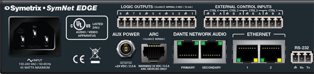
| Item | Description | Comments |
|---|---|---|
| Power (Main) | IEC 3 prong jack | Accepts power from detachable IEC power cable (100-240 VAC, 50-60 Hz, 45 Watts max). Connect only to a grounded power outlet. |
| Aux Power | Locking power plug | Accepts power from Mean Well power supply part number GS60A24-P1J fitted with a Switchcraft part number 767K plug or suitable 24 VDC / 2.0 Amp auxiliary power source. |
| ARC | RJ45 jack | Distributes power and RS-485 data to one or more ARC devices. Uses standard straight-through UTP CAT5 cabling. Warning! Refer to the RJ45 Warning for compatibility information. |
| Dante (Primary) | RJ45 jack | 1000 Base-T Ethernet port provides 128 (64x64) channels of Dante network audio. No functionality when no Dante card installed. |
| Dante (Secondary) | RJ45 jack | 1000 Base-T Ethernet port for redundant Dante network audio implementation in redundant mode, or for daisy chaining units without the need for extra switches and configuration in switched mode. No functionality when no Dante card installed. The Dante Secondary port mode is switched in the Network I/O Manager. |
| Ethernet (1 and 2) | RJ45 jack | 10/100 Base-T Ethernet ports for Composer host control and 3rd party accessory controllers over IP. Features auto-crossover sensing for direct device-to-device connections. Each connection may be used simultaneously to daisy-chain multiple Edge units or to connect to Composer and a control system at the same time without the need for extra switches or configuration. For 3rd party control, refer to the Control Protocol topic. A print version is also available on the Symetrix web site. |
| RS-232 | One (1) 3-pin 3.81 mm terminal block | Serial communications interface for a 3rd party accessory controller. Tx = Transmit or data out, Rx = Receive or data in. Port Settings: 57.6 kbaud (default), 8 data bits, 1 stop bit, no parity, no flow control. |
| Logic Outputs (1-8) | Twelve (12) position 3.81 mm terminal block | Eight (8) logic outputs with four (4) paired common ground pins. Logic Outputs go low (0V) when active, and are internally pulled high (5V) when inactive and can drive external LED indicators directly. The Logic Outputs are driven by Logic Output Control Modules places in the unit's design. Polarity and thresholds may be configured in software. |
| External Control Inputs (CTRL 1-4) | Twelve (12) position 3.81 mm terminal block | Four (4) analog control inputs able to be used as 4 potentiometer inputs or as 8 switch inputs (+3.3 VDC reference voltage supplied). External Control Inputs may be freely assigned to parameters in the unit's design. |
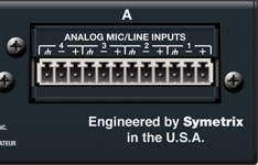
| Item | Description | Comments |
|---|---|---|
| I/O Card Slots | Four (4) configurable I/O card slots | Allows for up to 16 channels total of local I/O. |
Hardware Connections
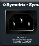 Power (Main): Connect the IEC connector end of the supplied AC cord to the receptacle on the rear of the Edge. Connect the AC connector end of the supplied AC cord to an AC power source that is of the correct voltage and frequency (100-240 VAC, 50-60 Hz). Use only the power cord and connector specified for the product and your operating locale.
 Aux Power: If desired, connect a suitable 24 VDC / 2.0 Amp auxiliary power source such as a Mean Well power supply part number GS60A24-P1J fitted with a Switchcraft part number 767K plug. Edge may be powered by either the Main or Aux power input. If both are present, Edge will favor the Main input, switching automatically to the Aux input should the Main input fail. When the Main input has been restored, Edge will switch back to it automatically.
 ARC: Using a standard straight-through CAT5 cable terminated with RJ45 connectors, connect your ARC Wall Panels or ARC-PSe to the ARC port according to the guidelines in the ARC Network Design section.
CAUTION: DO NOT plug the RJ45 connectors of an ARC Wall Panel into any RJ45 connector labeled "ETHERNET", "DANTE", "SYMLINK" or "COBRANET. Refer to the RJ45 Warning for compatibility information.
 Dante (Primary): If a Dante card is installed and using Dante network audio, connect the primary jack to directly to another Edge, 3rd party device, or Dante compatible switch using a standard straight-through CAT6 cable terminated with RJ45 connectors. For complete information on Dante network audio, network topologies, setup and configuration, refer to the Dante networking topics.
 Dante (Secondary): If a Dante card is installed and using Dante network audio and daisy chaining Edge units locally, or utilizing a redundant Dante network configuration, connect the primary jack to directly to another Edge or Dante compatible switch using a standard straight-through CAT6 cable terminated with RJ45 connectors. For complete information on Dante network audio, network topologies, setup and configuration, refer to the Dante networking topics.
 Ethernet: Using a standard straight-through CAT5 cable terminated with RJ45 connectors, connect either of Edge's Ethernet jacks to either your computer's Ethernet jack or to an Ethernet switch. Each connection may be used simultaneously to daisy-chain multiple Edge units or to connect to Composer and a control system at the same time without the need for extra switches or configuration. Refer to the Network Configuration section for more information.
NOTE: Edge's Ethernet jack will automatically sense a device-to-device connection so that a standard straight-through Ethernet cable may always be used. A cross-over cable is not required.
NOTE 2: The Ethernet connection is also available for 3rd party control. Refer to the Control Protocol topic. A print version is also available on the Symetrix web site.
 RS-232: Using a standard RS-232 cable wired straight-through terminated with a terminal block on one end and your connector of choice on the other, connect the Tx, Rx and Ground lines (typically pins 2, 3 and 5 in a DB9) to the appropriate pins on Edge and the controlling device. Edge is labeled from the device's perspective. Pin 3, or RS-232 Tx, needs to be connected to Rx on Edge. Pin 2, or RS-232 Rx needs to be connected to Tx on Edge.
Port settings: 57.6 kbaud (default), 8 data bits, 1 stop bit, no parity, no flow control.
NOTE: Default settings can be changed in Composer from the Remote Control Port Settings in the Upgrade Firmware/Hardware Settings dialog found under the Hardware Menu.
NOTE 2: Refer to the Control Protocol topic. A print version is also available on the Symetrix web site.
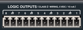 Logic Outputs: Using standard shielded twisted pair terminated with a terminal block on one end, you may connect up to eight logic controlled devices such as relays, LEDs or camera switchers. The Logic Outputs are driven by Logic Output Control Modules places in the unit's design. Polarity and thresholds may be configured in software.
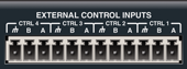 External Control Inputs: Using standard shielded twisted pair terminated with a terminal block on one end, you may connect up to two contact closures or one potentiometer to each four External Control Inputs. External Control Inputs may be freely assigned to parameters in the unit's design.
*** For information on I/O card connections, refer to the individual I/O cards' documentation.