Control Accessories
These modules provide miscellaneous functions involving control signals such as metering, allowing preset changes based on control signals and converting audio signals to control signals with programmable characteristics.
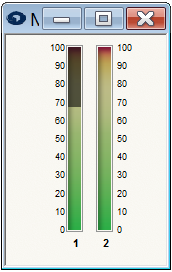 Control Meter Modules
There are modules that allow metering; 1, 2, 4, 6, or 8 control signals. These modules simply show the level of the connected control signals (0 to 100%) using peak-detecting meters. Use these modules any time you want to see the level of a control signal graphically or as trouble-shooting aids.
You can also use meter modules to read the value of a control signal from an RS-232/485 controller. Connect the control signal to a Control Meter module and assign the meter to an RS-232/485 controller.
Note: the Selected Wire meter also works with control signals. When the meter bar is visible, you can click on a control signal wire to see the level of that signal on the Selected Wire meter.
Preset Trigger
This module allows triggering a preset from a control signal. Programmable thresholds determine the level of the control signal required to trigger the preset. When the input control signal transitions from below the lower threshold to above the higher threshold, the preset is triggered. The threshold is specified in two parts to allow for hysteresis. The preset is triggered once every time a rising edge of the control signal is detected. If the control signal remains high, the preset will not be continually re-triggered. To trigger it again, the control signal must go below the lower threshold and then above the higher threshold.
Controls:
-
Threshold A. Determines the level below which the control signal must fall to be able to re-trigger the preset. Adjust using the slider or click in the text entry box to specify a numerical value.
-
Threshold B. Determines the level above which the control signal must rise to trigger the preset. Adjust using the slider or click in the text box to specify a numerical value.
-
Preset. Determines the preset number (1-1000) that will be triggered by the module. Adjust by clicking in the text entry box and specifying a numerical value from (1-1000).
-
Recall button. Pushing this momentary button triggers the preset manually. For the preset trigger to occur, you must be on-line and the hardware security level must be set to allow recalling presets from PC.
-
Input Level. A text display is provided showing the level of the input signal.
** Note: For clarity, it is advisable to set the Threshold B above the Threshold A. However, the module will still function the **
- same way if this is not the case.*
** Note: For the preset trigger to occur, the hardware security level must be set to allow recalling presets from remote**
- controls. this is true even when using the Recall button.*
Audio Level Detector
This module outputs a continuous control signal proportional to the peak or RMS level of the input audio signal. The module can be thought of as an audio-to-control converter.
Controls;
-
Peak/RMS buttons. Determines whether the input signals peak or RMS level is detected.
-
Log/Linear buttons. Determines the response of the peak detector. In both cases, an input signal level of 0dBFS generates and output of 100%. In linear mode, an input signal level of 50% or 6dB would generate 50% output, and so on linearly. In log mode, the output is linear in dB, that is every x dB drop results in a constant percentage drop by the output. In particular, for every 6dB drop in the signal level, the output decreases by 8.33%. When the input signal is below 72dBFS, the output will be zero in log mode. this can be expressed mathematically as out % = (In dBFS+72)/72. The appropriate setting of this parameter depends on what the control signal is controlling.
Note: If a different response shape is desired, use the linear setting and then process the output with one of the Taper
-
control modules.*
-
Response fader. Controls the response time of the output or equivalently the amount of filtering on the output. This control is similar to the attack/release times of a compressor. Setting a very fast time causes the output to closely track the waveform of the audio input. A slow time causes the output to track the slowly varying envelope of the output level of the module. With very slow settings, it will take many seconds to respond to the changes. This setting also affects the ballistics of the input meter.
Note: *If more precise control over the dynamics of the response is required, use the fastest setting and then process the *
-
output with a Ramp Processor module.*
-
*A meter shows the level of the audio signal input. The meter characteristics are controlled by the setting of the
Peak/RMS buttons and the response of the time slider. A text read-out displays the module's output (0-100%).
Audio Peak Detector
This module outputs a Boolean control signal that based on whether its audio input is above or below a fixed threshold. The threshold can either be based on the peak, or RMS level of the audio signal. The control signal output will be 100% if the audio signal is above the threshold and 0% if it is below. This module may be useful in determining if an audio signal is too hot or is clipping.
Controls:
-
Peak/RMS buttons. Determines whether the audio input signals peak or RMS level is detected.
-
Threshold fader. Controls the threshold of the detector in dBFS. Adjust using the slider or click in the text entry box to specify a numerical value.
A meter shows the level of the audio signal input. The meter characteristics are controlled by the setting of the Peak/RMS buttons. A LED indicator shows whether the output is off, or on (0 or 100%).